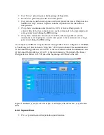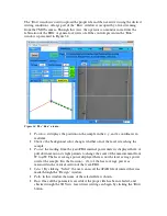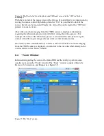
Figure 44. Starting position for the writing of the FBG.
Figure 45. The vertical knob of the TTR stage is used to control the z position of the fiber (a), while the
hidden knob below the LED is used to control the x and y positions of the fiber (b).
7.2
Producing the File
1.
Open the “Design” window in the
femto
FBG software.
2.
Choose a Gaussian “Profile Type”, a length of 7 mm, the Y-axis for travel, and
positive direction.
3.
Set the velocity at 100
µ
m/s.
4.
Set the step size at 10
µ
m, and the Min. and Max. values of the laser emission
output at 8% and 12%, respectively.
5.
These settings will produce a profile as shown in Figure 46.
6.
Press “Save” and choose the location where to save the file.


