4.9
EDH0162En1040 – 06/99
MM4005
Motion Control Tutorial
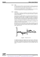
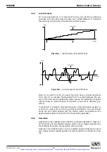
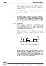
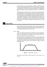
Fig. 4.7
— Hysteresis Plot.
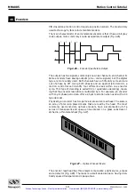
The error plot in reverse direction is identical with the first one but seems
to be shifted down by a constant error. This constant error is the
Hysteresis of the system.
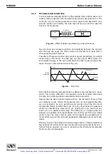
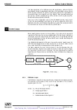
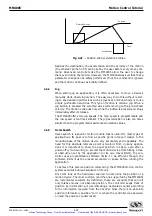
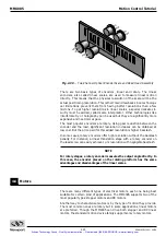
To justify a little more why we call this error Hysteresis, lets do the same
graph in a different format (Fig. 4.8). Plotting the real versus the ideal posi-
tion will give us a familiar hysteresis shape.
Fig. 4.8
— Real vs Ideal Position.
4.2.9
Pitch, Roll and Yaw
These are the most common angular error parameters for linear translation
stages. They are pure mechanical errors and represent the rotational error
of a stage carriage around the three axes. A perfect stage should not rotate
around any of the axes, thus the Pitch, Roll and Yaw should be zero.
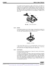
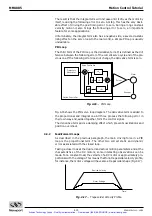
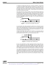
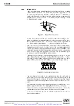
The commonly used representation of the three errors is shown in Fig. 4.9.
Pitch is rotation around the Y axis, Roll is rotation around the X axis and
Yaw around the Z axis.
Fig. 4.9
— Pitch, Yaw and Roll Motion Axes.
Pitch
Yaw
Roll
X
Z
Y
Real
Position
Trajectory (ideal position)
Ideal Plot
Real Plot
+
Position
0
Hysteresis
–
Error
Artisan Technology Group - Quality Instrumentation ... Guaranteed | (888) 88-SOURCE | www.artisantg.com

