EDH0162En1040 – 06/99
4.10
MM4005
Motion Control Tutorial
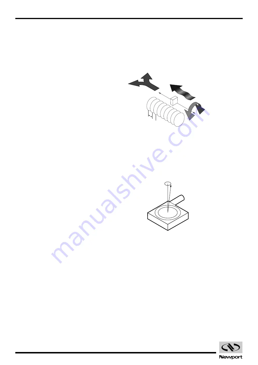
The problem with this definition is that, though correct, it is difficult to
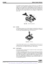
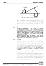
remember. A more graphical representation in presented in Fig. 4.10.
Imagine a tiny carriage driven by a giant leadscrew. When the carriage rolls
sideways on the lead screw, we call it a Roll. When it rides up and down on
the lead screw pitch, we call that Pitch. And, when the carriage deviates
left or right from the straight direction (on an imaginary Y trajectory), we
call it Yaw.
Fig. 4.10
— Pitch, Yaw and Roll.
4.2.10
Wobble
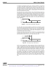
This parameter applies only to rotary stages. It represents the deviation of
the axis of rotation during motion. A simple form of Wobble is a constant
one, where the rotating axis generates a circle (Fig. 4.11).
Fig. 4.11
— Wobble.
A real rotary stage may have a more complex Wobble, where the axis of
rotation follows a complicated trajectory. This type of error is caused by
the imperfections of the stage machining and/or ball bearings.
4.2.11
Load Capacity
There are two types of loads that are of interest for motion control applica-
tions: static and dynamic loads.
The static Load Capacity represents the amount of load that can be placed
on a stage without damaging or excessively deforming it. Determining the
Load Capacity of a stage for a particular application is more complicated
than it may first appear. The stage orientation and the distance from the
load to the carriage play a significant role. For a detailed description on
how to calculate the static Load Capacity, please consult the motion con-
trol catalog tutorial section.
Screw Pitch
Roll
Pitch
Yaw
Artisan Technology Group - Quality Instrumentation ... Guaranteed | (888) 88-SOURCE | www.artisantg.com

