EDH0162En1040 – 06/99
4.22
MM4005
Motion Control Tutorial
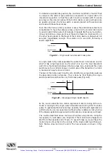
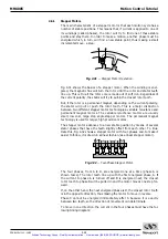
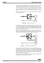
Fig. 4.28
— Optical Encoder Read Head.
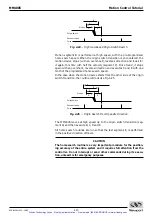
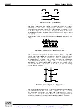
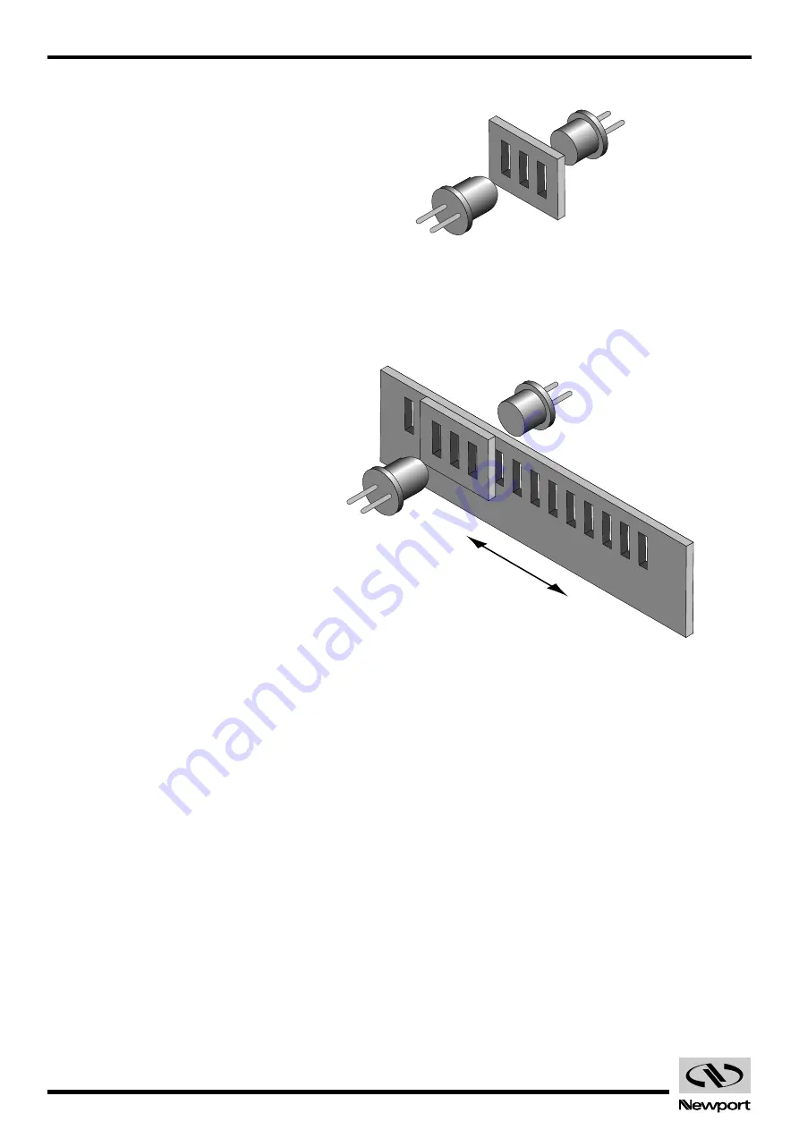
Combining the scale with the read head, when one moves relative to anoth-
er, the light will pass through where the transparent areas line up or
blocked when they do not line up (Fig. 4.29).
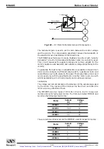
Fig. 4.29
— Single-Channel Optical Encoder Scale and Read Head Assembly.
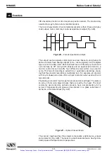
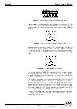
The detector signal is similar to a sine wave. Converting it to a digital wave-
form, we get the desired encoder signal. But, this is only one phase, only
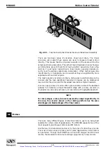
half of the signal needed to get position information. The second channel is
obtained the same way but from a mask that is placed 90% out of phase rel-
ative to the first one (Fig. 4.30).
Detector
Light Source
Artisan Technology Group - Quality Instrumentation ... Guaranteed | (888) 88-SOURCE | www.artisantg.com

