


5.5
EDH0162En1040 – 06/99
MM4005
Trajectory Functions Tutorial
Defining Trajectory Elements
Trajectories can be defined in many different ways. There is no universal
standard and most manufacturers of motion controllers use some degree
of custom conventions. For the MM4005, the guiding principal was to be as
user friendly as possible. Line and arc elements can be defined in more
than one way to offer the best solution for each application. The elements
are “seamed” together automatically and the entire trajectory is verified
before execution to guarantee its definition conforms to all rules.
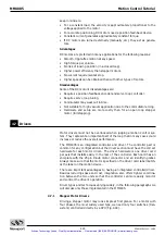
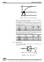
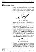
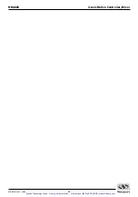
Fig. 5.1
— Trajectory example.
Figure 5.1 shows a trajectory example. Every trajectory must have an
“entry angle” defined. If the first element is an arc of circle, the entry angle
is the tangent to the first point of the arc.
Each element defined is identified by a number, starting from 1. The refer-
ences for synchronizing external events with the trajectory execution are
the starting and ending points of these elements.
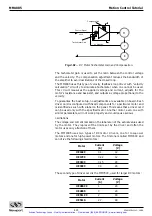
Line and arc elements can be sequenced in any order. Arcs can be followed
by arcs or lines and lines by arcs or other lines. An arc is automatically placed
by the controller such that its “entry angle” corresponds to the “exit angle” of
the preceding element to insure the continuity of the trajectory. But, when
defining a line by its X-Y end point, this responsibility falls on the user. The
end coordinates of the new line must be chosen such that the angle it defines
is identical to the “exit angle” of the previous trajectory element. Since we are
dealing with a coordinate system with finite resolution - the encoder resolu-
tion - getting a perfect match of the two angles is not always possible. For this
reason, a window of acceptable angle mismatch is defined, called “maximum
angle discontinuity”. This new parameter is measured in degrees and has a
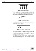
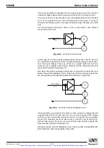
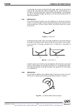
range of 0.001° to 10°. A trajectory can thus theoretically be build out of
straight lines that have less than 10° angle difference, as shown in Figure 5.2.
Fig. 5.2
— Contouring with lines only.
This practice is not recommended since each angle of discontinuity corre-
sponds to an instantaneous velocity change on both axes, which repre-
sents an infinite acceleration. The result is a shock (jerk) felt by the stages
and the load and a temporary following error pulse. The larger the angle of
discontinuity, the larger the jerk and the following error will be. Special
consideration must be given to both of these effects when increasing the
maximum discontinuity angle from its 0.001° default value.
1
2
3
4
5
Arcs
Lines
Entry Angle
5.4
Artisan Technology Group - Quality Instrumentation ... Guaranteed | (888) 88-SOURCE | www.artisantg.com


