8.9
EDH0162En1040 – 06/99
MM4005
4-Axis Motion Controller/Driver
C — Connector Pinouts
C.1
Labeling Conventions
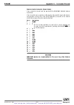
All pinout diagrams in this section use the following labeling convention:
AGND
⇒
Analog ground.
DGND
⇒
Digital ground.
N.C.
⇒
Not connected.
UTIL
⇒
Test/ utility signal.
DO NOT USE; MAY BE ENERGIZED.
I
⇒
Input.
O
⇒
Output.
WARNING
The company assumes no responsability for the use of any UTIL labelled
pin.
C.2
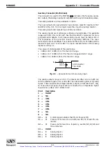
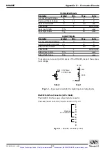
Power Inhibition Connector (9-Pin D-Sub)
This connector is provided for the wiring of one or more remote
Emergency Stop switches or Start switches. They will have the same effect
as the front panel MOTOR
or MOTOR
buttons.
The minimum rating for the switches should be 50 mA at 24 V and the maxi-
mum contact resistance should be less than 100
Ω
.
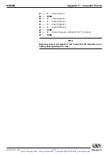
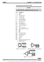
Pin #
Description
1
—
N.C.
2
—
UTIL
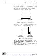
Start, switches must be self release push buttons. Wire the
switch contacts normally opened. The other side of the
switch should be connectd to DGND. If more than one
switch is installed, they should be connected in parallela.
3
—
I
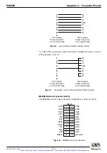
Emergency Stop, must always be connected to DGND dur-
ing normal controller operation. An open circuit is equiva-
lent to pressing MOTOR
on the front panel. Wire the
switch contacts normally closed. If more than one switch is
installed, they should be connected in series
4
—
N.C.
5
—
N.C.
6
—
DGND
7
—
DGND
8
—
DGND
9
—
N.C.
OFF
ON
OFF
Artisan Technology Group - Quality Instrumentation ... Guaranteed | (888) 88-SOURCE | www.artisantg.com

