EDH0162En1040 – 06/99
8.14
MM4005
Appendix C — Connector Pinouts
Optoisolated Inputs
Parameter
Symbol
Min.
Max.
Units
Low Level Input Voltage
V
il
0
5
V
High Level Input Voltage
V
ih
11
12
V
Input Current LOW
I
il
-5
-10
mA
Pulse Width
1
Servo Cycle
Input low to high
TP
lh
10
µsec
Input high to low
Tp
hl
10
µsec
Logical Outputs
Parameter
Symbol
Min.
Max.
Units
Low Level Output Voltage
V
ol
0
1
V
High Level Output Voltage
V
oh
30
V
Output Current LOW
I
il
-40
mA
Pulse Width
1
Servo Cycle
Output low to high
TP
lh
1
µsec
Output high to low
TP
hl
1
µsec
To assure good use and performances of the MM4005, respect these maxi-
mum ratings.
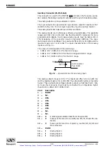
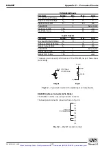
Fig. C.2
— Equivalent circuits for the digital input and output ports.
C.6
RS-232C Interface Connector (9-Pin D-Sub)
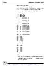
The RS-232 C interface uses a 9-pin Sub-D connector.
The back panel connector pinout is shown in Fig. C.3.
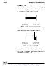
Fig. C.3
— RS-232C connector pinout.
1
2
3
4
5
6
7
8
9
Internal
Connections
In
1 k
Ω
LED
+12 V
Output
Input
Out 30 V max.
40 mA max.
Artisan Technology Group - Quality Instrumentation ... Guaranteed | (888) 88-SOURCE | www.artisantg.com


