16
Theory of Operation
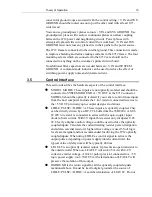
connect DGROUND to SYSTEM GROUND at the 8712 unless you are
just trying to make a simple hook-up to test operation of the 8712.
3.6
Output Connections
PULSE OUTPUT and PULSE RETURN connect the 8712 to the external
Picomotor connector. These signals carry a peak current of 2 A and 950 mA
(rms) with 15-
μs rise
-time and should be routed with care. Route one on top
of the other with minimum 0.015" trace width. Do not route any traces
parallel to PULSE OUTPUT or PULSE RETURN without at least 0.2" of
clearance.
Ground/power planes covering these traces can provide excellent shielding at
the risk of increased coupling of the pulse output to the shielding planes.
The 8712 incorporates current-limiting resistors to protect the customer’s
system from serious damage. If the PULSE OUTPUT is shorted, the resistors
will over-heat and open.
CAUTION
The 8712 is designed to drive a single Picomotor at a time. The
8712 can be used to control multiple Picomotors using external
relays or switches but only one Picomotor at a time.
If this is done, DO NOT SWITCH CONNECTIONS WHILE THE
8712 IS ENABLED.
Electrically, Picomotors behave like capacitors with a very low
leakage resistance. Thus, they can retain significant voltage if
an external switch disconnects the Picomotor while the 8712 is
outputting a drive voltage. If an 8712 which is driving a low
voltage is subsequently connected to a previously charged
Picomotor, the energy stored in the Picomotor may be sufficient
to damage the 8712.
3.7
Sockets
The 8712 can be connected to your printed circuit board with female header
sockets:
These headers come in standard lengths of 36 or 72 pins and can be cut as
needed for the 8712.
Make
Model
Digi-Key #
3M
80620078958
929850-01-36-ND
Mill-Max
801-036-10-012000
ED7636-ND
Mill-Max
801-93-050-10-0001
ED7150-ND


