Initial Setup
33
4.5
Connecting 8742 to a Computer via Ethernet
4.5.1
Connecting to a Router
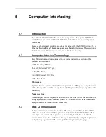
The 8742 Controller/Driver can be connected to an Ethernet Router. Attach the
computer Ethernet cable to the same router. If desired, the router can be attached to
a WAN (Wide Area Network) so that the computer can also be connected to
internet, or company network.
By default, the 8742 Controller/Driver is set for DHCP (Dynamic Host
Configuration Protocol). This means that, when connected to a router which is set in
DHCP mode, the router will automatically assign it a local IP address from the
router address pool. The computer will also receive a local IP address. The IP
address normally will be in the range of 192.168.1.1 to 192.168.255.255. Check
your router settings to verify the IP address pool.
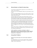
As soon as both units, 8742 and computer, are connected to the router the Picomotor
Controller/Driver is ready to communicate with the computer. The discovery utility
will automatically find the IP address of the 8742 Controller/Driver and the user can
start sending commands to the unit. See Section 5 for details.
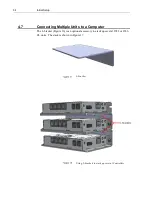
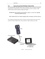
If several 8742 units have to be connected to the same computer the user can
connect them individually to an Ethernet hub or router. Alternatively, the first unit
can be connected to the router (or computer) with subsequent units daisy-chained as
described in Section 4.7.3 Using RS-485 LAN to Daisy-Chain.
4.6
Picomotor Connections
Each Model 8742 controller/driver can control one of four 4-pin RJ-22 single output
ports for use with any single-channel Picomotor actuator at any given time.
RJ-22 motor connector pinouts are as follows:
Pin-1
Not Connected
Pin-2
Ground
Pin-3
Motor
Pin-4
Ground
The model 8725 multi-axis adapter can be used to connect the 4-pin RJ-22 output
ports to New Focus™ Picomotor products with 6-pin RJ-11 connectors.
Summary of Contents for New Focus Picomotor 8742
Page 1: ...Picomotor Controller Driver User s Manual Model 8742 ...
Page 53: ...Computer Interfacing 53 Cycle Tab Cycle Motion ...
Page 54: ...54 Computer Interfacing Terminal Tab Command Line Terminal ...
Page 57: ...Computer Interfacing 57 Options Window Connection Options Setup ...
Page 58: ...58 Computer Interfacing Properties Window USB and Ethernet Properties ...
Page 59: ...Computer Interfacing 59 Controller Scan Scan RS 485 LAN ...
Page 61: ...Computer Interfacing 61 Device Address Window View Change Controller Address ...


