background image

Pp

Pulse

Scout2 Autocorrelator

Test

PScout2 Series User's Manual

Summary of Contents for PScout2 Series

Page 1: ...Pp PulseScout2 Autocorrelator Test PScout2 Series User s Manual...

Page 2: ...n Germany Importer Newport Corporation 1791 Deere Avenue Irvine CA 92606 United States of America Standards Applied Compliance was demonstrated to the following standards to the extent applicable BS E...

Page 3: ...the sole responsibility of A P E Angewandte Physik Elektronik GmbH Speci cally products manufactured do not contain the substances listed in the table below in concentrations greater than the listed m...

Page 4: ...ting the PulseScout2 particularly Section 1 on safety instructions The PulseScout2 is only to be used as described in this manual Differing use may endanger safety and voids warranty CAUTION USE OF CO...

Page 5: ...he product s enclosure that may be of suf cient magnitude to constitute a risk of electrical shock and to indi cate possible risk of equipment damage Disposal The PulseScout2 ful lls the European Dire...

Page 6: ...surement 23 4 2 1 Alignment of the Input Beam 23 4 2 2 Finding the Autocorrelation Trace 25 4 2 3 Crystal Angle Tuning and Phase matching 26 4 2 4 Zero Scan Range 27 4 2 5 Further Alignment Optimizati...

Page 7: ...n Issues 44 6 2 Maintenance 45 6 2 1 Cleaning 45 6 2 2 Storage of SHG Crystal 45 6 3 Technical Support 45 6 3 1 Service 46 6 3 2 Obtaining Service 46 6 3 3 Warranty 46 6 3 4 Service Form 47 A Fitting...

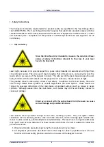
Page 8: ...s of light The greatest concern when using a laser is eye safety In addition to the main beam there are often many smaller beams present at various angles near the laser system These beams are formed...

Page 9: ...that allows for save handling Caution When opening the optical head top cover a laser beam might emerge in upward direction if the input beam to the unit is not properly blocked nor the laser switche...

Page 10: ...es can occur at the photomultiplier detector unit and its power supply 1 3 Electromagnetic Compatibility The European requirements for Electromagnetic Compliance EMC are speci ed in the EMC Di rective...

Page 11: ...of three components 1 PulseScout2 optical head 2 scoutLink controller 3 Control Software Figure 2 1 PulseScout2 optical head left and scoutLink Controller Unit right The Control Software is operated...

Page 12: ...ge 150 fs 15 ps 150 fs 500 fs 1 5 ps 5 ps 15 ps Measureable pulse width 20 3500 fs selectable ranges For all detector types Min input power 2 mW Max input power 250 mW or 1 J which ever results in the...

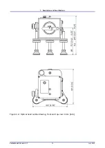
Page 13: ...2 Description and Speci cations Figure 2 2 Optical head outline drawing front and top view in mm inch PulseScout2 Version 1 1 13 July 2015...

Page 14: ...the Control Computer Minimum system requirements Windows 7 1 500 MB hard disc space Pentium IV or equivalent processor 2 GB of RAM USB port Screen resolution of 1024 x 768 pixels 1 Windows is a regis...

Page 15: ...eration Ensure reasonable transport conditions free of major shocks jolt or fall protect against frost Use original packing material for relocation Allow at least six hours for acclimatization of all...

Page 16: ...seScout2 detector module incl crystal packed separately 3 2 Inspection on Receiving On receipt of the PulseScout2 autocorrelator system 1 Inspect the packing material for signs of rough handling or da...

Page 17: ...OWER power switch 2 AUX auxiliary connector not used 3 TRIGGER IN trigger input 4 DC IN DC power connector connect to 12 V DC power adapter 5 USB USB connector connect to PC 6 Status LED 7 OPTICS 25 p...

Page 18: ...stal mount cover 2 Beam shutter S1 3 Beam shutter S2 Figure 3 3 PulseScout2 optical head beam shutters and crystal mount cover 3 4 Installation of the scoutLink Control Software Important Before conne...

Page 19: ...lled in the optical head of the PulseScout2 It comes in a separate box to protect it from damage and has to be installed before using the PulseScout2 for the rst time Please note that you will need to...

Page 20: ...st of available detector modules See also Table 2 1 on page 12 Change the detector unit if necessary according to the instructions in this paragraph Caution Do not expose the PMT of the detector modul...

Page 21: ...ith the scoutLink controller OPTICS port using the supplied 25 pin D Sub connection cable Always use the original cable 2 Connect the scoutLink controller USB port with your computer using the supplie...

Page 22: ...ut2 has been established when the serial number of the unit is shown in the window title If communication is established the info window displays the status ACF 0 fs in the upper left corner of the me...

Page 23: ...repetition rates and high energy laser ampli er systems For such con gurations it is strongly recommended to keep the input pulse energy below 1 J to avoid damage of the autocorrelator Once an autoco...

Page 24: ...all the way in for collinear operation see Figure 4 3 In collinear mode a signal increase from the autocorrelator can be seen if the crystal is aligned at the proper angle even if the two replica beam...

Page 25: ...e a small portion of second harmonic light coincident with the fundamental laser pulse aligned to the PulseScout2 and this small amount of light may overlay the in comparison weaker second harmonic si...

Page 26: ...elp and tips refer to Section 6 1 Troubleshooting on page 43 4 2 3 Crystal Angle Tuning and Phase matching Tuning SETUP Tuning refers to the process of adjusting the angle of the crystal with respect...

Page 27: ...position Repeat this step with the other shutter where the signal drop should be the same If both shutters are closed simultaneously the signal should go down to almost zero only the background noise...

Page 28: ...meter arms can be changed between 0 6 mm observable at the alignment window next to the input aperture the moving spot has to be at the left side of the x spot After changing the beam distance also th...

Page 29: ...user de ned folder Setup quick save Chooses a default le name and location for the Quick save function Load Data Loads and displays previously made autocorrelation traces The loaded trace is shown si...

Page 30: ...e of choosing a tting function the Info box shows additional information such as the FWHM of the MSE Mean Square Error of the t For more details on tting the ACF refer to Appendix A on page 48 Average...

Page 31: ...he following parameters are available Trigger Level mV The voltage level at which the scoutLink registers an incoming trigger sig nal is set here in mV Change this value if a trigger signal is not rec...

Page 32: ...d Use this setting to center the ACF Note Click with the mouse between the digits of the arb number displayed here to set the step width Reset O set Resets changes made by the user to factory settings...

Page 33: ...pper right corner of the Control Software Zooming and Panning In the lower right corner of the Control Software there are four addi tional buttons that allow to activate the cursors to zoom intensity...

Page 34: ...alue see Section 4 3 3 Be aware that setting the trigger lever too low may cause the PulseScout2 to recognize electronic noise as trigger signal and thus lead to false measuring behavior To manually s...

Page 35: ...outines with any programming language C Python LabView Octave MatLab Excel It is recommended to use a command line terminal to test the connectivity to the device and to get a better understanding of...

Page 36: ...ware Scan range too low If the chosen scan range is too low with respect to the detected width of the autocorrelation trace a part of the measured autocorrelation might be clipped Without a robust det...

Page 37: ...for a precise determination of the ACF value see Figure 4 17 Note that an error message indicating a too large scan range will appear in the Info box This is not the case in the Figure below Figure 4...

Page 38: ...etec tor The consequence is clipping of the measurement trace see Figure 4 18 Clipping prevents the software from calculating the ACF value and must be avoided Figure 4 18 A too high signal leading to...

Page 39: ...the given dynamic range This can lead to an erroneous measurement of the FWHM value due to the low signal to noise ratio see Figure 4 19 Figure 4 19 A too weak signal leading to a low dynamic is indi...

Page 40: ...be cut off to the left or right of the scan range If the measured autocorrelation trace deviates too much from symmetry the info box shows an Asymmetric error message see Figure 4 20 Figure 4 20 ACF c...

Page 41: ...e 5 1 Also note that the lter is automatically switched off in triggered measurement mode Figure 5 1 Collinear ACF measurement with lter OFF left and lter ON right 5 3 Change of Wavelength Range Cryst...

Page 42: ...g a suppression of the ACF peak without cutting it off The ACF may look similar to an ideal ACF but will be arti cially broadened To prevent this it is strictly recommended to operate triggered mode w...

Page 43: ...l compare with sensitivity speci cations delay zero position outside of check at wider scan ranges scan range check and correct for delay zero position see test report No clear ACF wrong scan range ch...

Page 44: ...Trigger Mode If the trigger frequency changes during triggered measurement to a value higher than 100 kHz the ACF may become distorted or the software may prompt the user to restart it ACF Fit Someti...

Page 45: ...Scout2 are slightly hygroscopic Store crystals that are not in use in an airtight box along with silica gel If you do not use the autocorrelator for a long time it is recommended to remove the crystal...

Page 46: ...occurring in transit and is not obligated to accept products returned without an RMA E mail rma service newport com When calling Newport Corporation please provide the customer care representative wit...

Page 47: ...ation see section 6 3 Name Return Autorization Please obtain RA prior to return of item Company Address Date Country Phone Number P O Number Fax Number Item s Being Returned Model Serial Description R...

Page 48: ...Figure A 1 Gaussian function e t2 and its normalized autocorrelation e 2 2 dotted line Equating the normalized Gaussian functions with 1 2 gives the time value at half amplitude G a 1 2 a p ln 2 A 3...

Page 49: ...4 4 2 dotted line Equating the normalized Lorentzian functions with 1 2 gives the time value at half amplitude L a 1 2 a 1 A 8 LACF b 2 1 2 b 2 A 9 The quotient of these time values supplies the tran...

Page 50: ...g the normalized functions with 1 2 gives the time value at half amplitude S a 1 2 a 0 881374 A 12 LACF b 3 4 1 2 b 1 35979 A 13 The quotient of these time values supplies the transformation factor be...

Page 51: ...rsion Detailed information about the SCPI is found at www ivifoundation org The autocorrelator will execute the following commands IDN Get Device Identi cation idn Device Information Vendor Devicename...

Page 52: ...Enable Register value SRE Register Value as integer range 0 255 Example SRE 127 SRE Get Service Request Enable Register value SRE Register Value as integer range 0 255 Example SRE ESR Get Event Status...

Page 53: ...as integer Example INIT BUSY Get Device Busy Status busy SCPI BUSY Status 8 Bit unsigned as decimal upper 4 Bits are always 0 Bit0 IDLE Bit1 New data available Bit2 Measurement running Bit3 Curve t ru...

Page 54: ...000 S99999 as string Example scoutlink sys snumber scoutlink SYSTEM SOFTWARE scoutlink SYS SOFTWARE Get Software Version version Software Version as string Example scoutlink sys software scoutlink SYS...

Page 55: ...ents as integer range 0 4 Example scoutlink sta average 1 scoutlink STATUS AVERAGE scoutlink STA AVERAGE Get number of measurements used for averaging number Number of Measurements 0 Averaging OFF 1 2...

Page 56: ...nt 1 Measurement running 0 Measurement paused as string Example scoutlink sta start scoutlink STATUS FILTER status scoutlink STA FILTER status Set Status of ACF Filtering status as string Example scou...

Page 57: ...utlink XTAL TUN number Set Crystal Position number Crystal Position as integer Example scoutlink xtal tuning 1234 scoutlink CRYSTAL TUNING scoutlink XTAL TUN Get Crystal Position number Crystal Positi...

Page 58: ...30000 30 ps optional as integer unit fs Example scoutlink mot scr scoutlink DETECTOR GAIN value scoutlink DET GAIN value Set PMT Gain value Function has no effect if standard optics units w o a PMT i...

Page 59: ...ger Level as integer range 100 5000 unit mV Example scoutlink tri lvl scoutlink TRIGGER LEVEL scoutlink TRI LVL Get Trigger Level level Trigger Level as integer range 100 5000 unit mV Example scoutlin...

Page 60: ...ance as integer unit Ohms Example scoutlink tri imp scoutlink ACF DATA scoutlink ACF RAW_DATA Get ACF Data acf ACF Data as SCPI Block Interleaved Array of Double Values y1 x1 y2 x2 yN xN x Delay ps y...

Page 61: ...lons AVG Xmax Xmin Ymax Ymin as string Example scoutlink acf meandata scoutlink ACF FWHM Get FWHM Value fwhm FWHM Value as double Example scoutlink acf fwhm scoutlink ACF FITFWHM Get tted FWHM Value f...

Reviews: