3.
Installation
3.3.
System Controls and Indicators
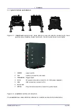
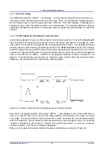
Figure 3.1.:
Pulse
Scout2
optical head - beam distance screw and detector module (left), focus
position screw (middle), shutter buttons S1, S2 and crystal mount cover (right)
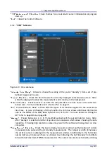
1 POWER
power switch
2 AUX
auxiliary connector (not used)
3 TRIGGER IN trigger input
4 DC IN
DC power connector (connect to 12-V DC power adapter)
5 USB
USB connector (connect to PC)
6 Status LED
7 OPTICS
25-pin D-Sub connector (connect to optical head)
Figure 3.2.:
scout
Link
controls and connectors
The
scout
Link
has a status LED that indicates its condition as listed in the table below:
Pulse
Scout2 Version 1.1
17
July 2015

