background image

User’s Guide

Quantum Efficiency Measurement Solution

QuantX-300

700514  February 2019

Summary of Contents for QuantX-300

Page 1: ...User s Guide Quantum Efficiency Measurement Solution QuantX 300 700514 February 2019...

Page 2: ......

Page 3: ...pter 1 Introduction and Specifications 7 Safety Considerations 7 Initial Inspection 8 Product Overview 12 Features of the QUANTX 300 13 Specifications 14 Options and Accessories 15 Chapter 2 Assembly...

Page 4: ...51 Reflectance Measurement Controls 53 Diffuse Measurement Controls 55 Sample Measurement Controls 56 Chapter 5 Calibration and Measurement 59 System Configuration 59 Monitor Detector Calibration 60...

Page 5: ...nt Warning indicates a potentially dangerous situation which can result in serious injury or death Safety Symbols This section describes the safety symbols and classifications Technical specifications...

Page 6: ...material and workmanship for a period of one year from date of shipment During the warranty period Oriel Instruments will repair or replace the unit at the discretion of Oriel Instruments without char...

Page 7: ...metal bands Send the instrument to Oriel Instruments Clearly write the return authorization number on the outside of the box and on the shipping paperwork Oriel Instruments recommends you insure the s...

Page 8: ...Return Material Authorization RMA number Please mark this number on the outside of the shipping box The customer or their shipping services are responsible for any shipping damage when returning the i...

Page 9: ...s If any of the following symptoms exist or are even suspected remove the QUANTX 300 from service Do not use the QUANTX 300 until trained service personnel can verify safe operation Visible damage Sev...

Page 10: ...s as four separate packages 1 QUANTX 300 Instrument Package a Primary QUANTX 300 instrument body PN 603618 QUANTX 300 Instrument 2 Sample Stage Package a Sample Stage PN 603384 b Magnetic Probe Plates...

Page 11: ...ing Brackets x4 PN PS F 1 4 20x1 inch Screws x4 PN A1JD1432QAZB M6 1 0 x 25 mm Screws x4 PN C1JR06025G Hex Ball Drivers 3 16 9 64 1 8 3 32 1 16 PN 90 11 044 90 11 047 90 11 046 90 11 044 90 11 042 Mou...

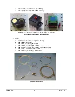
Page 12: ...03621 Reference Detector and SAMPLE QESI Silicon Test Sample Cell d Cables AC Power Cable varies by region not shown USB Cable PN 70044 BNC Cable 24 inch x2 PN 403230 BNC to SMA 36 inch x2 PN 403391 B...

Page 13: ...omputer Package f Laptop Computer PN 800244 g Laptop Power Cable included with 800244 h USB Thumb Drive Software Documents and Data Manual Certifications Calibration Standards Data QUANTX Software Ins...

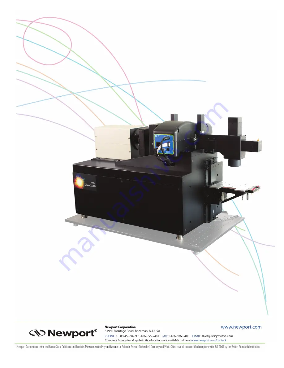
Page 14: ...components with integrated light source monochromator detectors electronics software and even the computer The QUANTX 300 incorporates a patented detector geometry using a beam splitter allowing for s...

Page 15: ...omator with automated filter selection Achromatic optics maintains spot size throughout the entire spectral range Wavelength range 325 nm to 1800 nm User friendly software interface for calibration an...

Page 16: ...100k 1M 10M AC Gain Settings 1 10 100 1000 Sample Current Range 10nA 1 0A Voltage Bias 10 V up to 0 5 A Voltage Bias Resolution 0 1 V ELECTRICAL MECHANICAL SPECIFICATIONS Compliance CE compliance Siz...

Page 17: ...C Electrical Contact Probe Kit Magnetic PVIV PROBE KIT Light Biasing Kit Delivers white or filtered sample biasing illumination IQE LIGHT BIAS Vacuum Pump for sample stage or IQE 200B TC VAC PVIV VAC...

Page 18: ...February 2019 16 QUANTX 300...

Page 19: ...PN 603618 4 Optical bench mounting brackets PN PS F b 4 1 4 20x1 PN A1JD1432QAZB or M6 1 0 x 25mm screws PN C1JR06025G Tools needed to complete this step 9 64 Allen Wrench Procedure Place the QUANTX 3...

Page 20: ...ge PN 603354 Procedure Locate slide rail on QUANTX 300 on the right side of the instrument Sample Stage Slide Rail Unscrew thumb screw on left side of sample stage until only a few threads are holding...

Page 21: ...stage in the right hand place right side of stage into right side of slide rail Right Side of Sample Stage Aligned Pivot the sample stage to align the left side of the sample stage to the left side o...

Page 22: ...Tools needed to complete this step 1 Phillips Screwdriver not included Gloves not included to prevent oils from contaminating the lamp Before beginning this step ensure that the main power supply is d...

Page 23: ...top cover of the lamp housing 4 Remove the lamp housing cover Remove the lamp cage connector retention cover by removing the thumbscrew and set aside Lamp Cage Retention Cover and Thumbscrew Gently s...

Page 24: ...n and Removal Gently lower the lamp into the lamp cage Rotate it slightly and tilt it back so that the anode lead wire clears the lamp seating plate Guide the reflector rim into the recessed lamp seat...

Page 25: ...r into the cutout in the rear of the lamp cage while connecting it to the lamp connector o Be careful not to stress the wires at the lamp ends o Note that the connector is keyed for proper polarity La...

Page 26: ...wer Cable Region specific USB Cable Laptop Computer Laptop Power Cable 240VAC Fuses 1 5A PN 15 29 152 BNC Cables 24 inch x3 PN 403230 Tools needed to complete this step Allen Wrench 1 8 PN 90 11 046 i...

Page 27: ...amp Power Connection Ensure the lamp power cable is connected Lamp Power Switch and Connector Rear Panel Connections Before beginning this step inspect power cables to ensure the correct terminals exi...

Page 28: ...ctance detector and the reflectance BNC connector on the rear panel labeled REFLECTANCE A in the figure above o Connect a 36 BNC cable between the SMA connector on the monitor detector and the monitor...

Page 29: ...top Computer Connect the Laptop Power Cable between the Laptop Computer power supply and a live outlet Connect the QUANTX 300 Power Cable o While pressing the tab remove the fuse holder from the power...

Page 30: ...X 300 system power switch on the rear panel to the on position Listen for the chopper wheel to begin rotating To avoid heating of the chopper wheel it must be spinning before turning on the lamp Power...

Page 31: ...software will launch and initiate operation QUANTX Software Icon QUANTX 300 Shut Down This procedure describes the correct safe way to shut down the QUANTX 300 STEP 1 STOP THE QUANTX SOFTWARE The sof...

Page 32: ...inging the temperature of the lamp down to a safe level before stopping Do not continue the shut down procedure until the fans have stopped STEP 3 POWER OFF SYSTEM AND DISCONNECT CABLES As noted above...

Page 33: ...NITOR on the output optics assembly to the MONITOR port Diffuse This port is provided for future upgrades to the system Nothing is connected to this port at this time Light Bias Output This provides a...

Page 34: ...ut to PV cell The sense wires measure the true voltage drop at the cell and exclude the additional voltage drop of anode cathode wires 4 wire connector configured as a 2 wire connection by jumping the...

Page 35: ...age to aid the user in correctly placing and connecting to the sample The installation of the stage is described in the assembly Instructions The Tip Tilt stage can be adjusted 2 5o from front to back...

Page 36: ...uum pump Contact Points There are 6 contact jacks mounted on the platform The jacks are isolated from each other and from the instrument ground The black contact is tied to the polished sample stage p...

Page 37: ...reached The standard includes a focusing point on the front face to aid in setting the proper working height of the stage 1 First place the standard on the stage with the focusing point small rectangl...

Page 38: ...nd low reflectance standard surfaces are the same height as the target etched on the holder The test sample also matches the height of the focal plane so little to no vertical stage adjustment is nece...

Page 39: ...Please take great care of the detector by keeping the cover on unless it is in use not dropping it or touching contaminating the detector area This may cause the detector to perform differently from...

Page 40: ...ify system performance specifications Newport recommends using calibrated reference cell model 91150V for this purpose This reference cell is accredited to the ISO IEC 17025 standard by our PV Calibra...

Page 41: ...that ships with the system comes with the software pre installed To launch the software double click on the desktop icon Main Screen When the software is launched it opens the main control screen show...

Page 42: ...to provide monochromatic output Filter 1 2 610nm Filter 2 3 1030nm 6 Monochromator Settings Set the start stop and step wavelength of the measurement scan 7 Reflectance Detector Settings for measureme...

Page 43: ...proportional to the current from the reflectance detector Sam Sample V Lock in voltage proportional to the current from the sample 12 Start Stop Scan Turns red during scan Click to stop scan with the...

Page 44: ...original size 13 Graph Manipulation Tools Zoom in using boundary zoom in using region pan graph zoom out to full scale Double left click on graph to zoom back out 14 Plot Legend When multiple plots ar...

Page 45: ...the chopper frequency Slow chopping frequencies can result in a longer scan time but may be necessary for PV cells with slow response time Chopper Control Window Indicator turns green when chopper rot...

Page 46: ...February 2019 44 QUANTX 300...

Page 47: ...light through unless the lower wavelength light is filtered out The filters switch into place automatically as the monochromator tunes past the switch over wavelength The default settings will work f...

Page 48: ...dard 5 position filter wheel of which only 3 positions are being used with the additional two positions reserved for wavelength expansion Therefore the wheel will take longer to switch from position 3...

Page 49: ...3 10CGA 1000 No filter in position 1 Cut on filter at 590nm Cut on filter at 1000nm Monochromator Control Click Monochromator Icon to manually set wavelength set scan start stop and step size wavelen...

Page 50: ...be entered manually or by using increment decrement arrows Click on the Go button for the setting to take place After a moment the actual wavelength of the monochromator is shown NOTE The actual wavel...

Page 51: ...narrow scan results you can increase to the full wavelength range confident the results will be accurate IMPORTANT Click on the SET button for these settings to take effect Function Sets the start sto...

Page 52: ...t the switch over wavelength is set to a default of 1110nm for the IQE 200B so no switch takes place Grating 2 will be used to scan from 1110 to 1800nm Function Sets the switch over wavelength for the...

Page 53: ...brated reference detector More specifically the signal from the monitor detector directly correlates to the optical power at the sample at each wavelength step Once calibrated measured signals from th...

Page 54: ...loor of 0 5 NEW Starts a new scan and stop the scan before it reaches the stop wavelength if desired 6 Load Previous option to quickly load the last calibration of the calibrated reference detector if...

Page 55: ...reflectivity off a known high reflection standard as a function of wavelength Following this measurement a second screen guides the user through a similar measurement off a known low reflection standa...

Page 56: ...ed about 0 or DC signal floor of 0 5 NEW Starts a new scan and stop the scan before it reaches the stop wavelength if desired 6 Load Previous option to quickly load the last calibration of the high re...

Page 57: ...last calibration 7 Reflectivity x100 graph of the reflectivity of the low reflectance standard as a function of wavelength nm 8 Active Volts graph of the chopped optical signal as function of time 9 S...

Page 58: ...ngs needed to measure the reference detector during calibration and your PV samples It includes voltage bias control for your sample sample connection to the system gain and an enable disable switch t...

Page 59: ...ote The sample needs to be enabled 5 for an accurate bias voltage readout 5 Sample Control switches the sample connection from the safety circuit to the sample circuit in the instrument Do not connect...

Page 60: ...DC gain alone DC Gain 100 1000 1K 10K 100K 1M 10M AC Gain 1 10 100 1000 Coupling AC centered about 0 or DC signal floor of 0 8 Set wavelength display present wavelength of the output beam 9 Shutter Co...

Page 61: ...he QUANTX 300 is set up and running and the QUANTX 300 software application has just been launched and is in control of the system Please configure the system and follow the calibration steps listed b...

Page 62: ...nce detector on the stage such that the beam is focused on the platform on the side of the detector housing Connect the detector to the sample BNC port using the 24 BNC SMA cable 3 Adjust the height o...

Page 63: ...ommended for calibration Scan time 10 50 40 high accuracy calibration Scan time 18 30 Set Bias Voltage 0 for calibration using a enter 0 in bias voltage text box b click on zero bias Verify input sele...

Page 64: ...uire you to reduce the gain and rescan The noise floor is 10 4 below signal for high dynamic range of the signal Active signal should have square tops bottoms with amplitude of 1 2 Vpp Note if the cho...

Page 65: ...h as 555nm to and check beam is centered on calibrated reference detector input port Adjust gain settings to Mode Basic Gain 100K Click on the Active tab to view the chopped signal Verify the amplitud...

Page 66: ...calibrated as indicated by a green border surround the detector value on the main screen NOTE The system does not check the accuracy of the calibration The green border only indicates the process of c...

Page 67: ...anged 1nm Calibrated with supplied Reference Detector Calibrated with different Reference Detector X Calibrated with supplied Reflectance Standards Calibrated with different Reflectance Standards X Sa...

Page 68: ...red on High Reflectance standard Adjust gain settings to Mode Basic Gain 100K Click on Home to return to main screen 4 Click on the Reflectance Detector icon to enter the reflectance calibration scree...

Page 69: ...f the vertical axis and deselect autoscale Click on the NEW button to begin calibration of the High R View the raw detector signal lockin voltage as the wavelength scans by selecting the Scan tab in t...

Page 70: ...es at the prompt to overwrite last calibration with the new reflectance calibration Check calibration on Calibration tab The calibration contains a slope m and intercept n for each step in wavelength...

Page 71: ...was made the same thickness as the calibrated reference standard so no adjustment should be necessary for stage height Make sure the surface of the cell is clean and free of dust Center the sample cel...

Page 72: ...t Center the beam between the bus bars on the sample cell If the beam overlaps a bus bar the SR and EQE response will be too low and the reflectivity Rs will be too high If beam overlaps the bus bars...

Page 73: ...nded for calibration Scan time 10 50 40 high accuracy calibration Scan time 18 30 Set Bias Voltage 0 for this PV sample measurement using a enter 0 in bias voltage text box b click on zero bias Verify...

Page 74: ...he supplied 1 5 tube on top of the detector Translate the PV sample so the beam lies between the bus bars The bus bars will reduce the accuracy by a Lowering efficiency of PV sample because the bars d...

Page 75: ...mple Sample Setting Description SR Spectral Response A W EQE External Quantum Efficiency x100 IQE Internal Quantum Efficiency x100 Rs Specular Reflectance x100 Mon Raw Monitor Signal Volts lockin valu...

Page 76: ...elimited text format Print visible graph Prints the graph you are currently viewing to your default printer if connected Jsc Short Circuit Current Density values calculated from recent scan at various...

Page 77: ...le measurement by typing in the value in the input box Enable Sample to verify a bias is being added across the anode cathode of the PV sample when it is electrically connected to the circuit Sample v...

Page 78: ...in comparison to no bias voltage applied to the sample Notice that for this sample the bias voltage has very little effect on the quantum efficiency of the sample 10 To see an earlier measurement loa...

Page 79: ...es that which is reported by the software This should be done before your first measurements when the system is first received It is also recommended whenever the QUANTX 300 is moved significantly e g...

Page 80: ...February 2019 78 QUANTX 300 3 Adjust the slit width to 75 m This is 7 5 on the micrometer scale...

Page 81: ...ain and AC Coupling as shown below 5 In the Monochromator screen set the scan parameters to start at 800nm stop at 900nm with 1nm steps 6 Click the start scan button to run the scan 7 When the scan is...

Page 82: ...calibration Reduce the Monitor detector gain to Gain Ctl Basic and Basic Gain 100k Then return the monochromator input and output slits to 750 m 75 on the micrometer scale or 1 5 full clock wise revol...

Page 83: ...wo peaks are off of their ideal value by 1 nm This indicates that the monochromator calibration is slightly off The peaks should be at 823nm and 882nm but they are actually at 824nm and 883nm 2 Close...

Page 84: ...y detected and the program should initialize 4 We will use the peak found at 824nm to correct the wavelength calibration of the monochromator 5 Input 824 into the Set Wavelength field of the monochrom...

Page 85: ...ck the Calibration button 7 Since the peak found at 824nm should actually be at 823nm input this into the Calibrate Wavelength field of the Calibration Settings popup window and press Enter Press OK i...

Page 86: ...cedure above The peaks should now appear at the correct locations 9 If the monochromator cannot be recalibrated such that the Xenon emission lines appear in the correct location or if the wavelength i...

Page 87: ...Maximum bandwidth recommended by ASTM E1021 06 It is recommended to match the FWHM bandwidth with the wavelength step size for best resolution and maximum output power of the QUANTX 300 Recommended s...

Page 88: ...y bumping it Repeat for the entrance slit adjustment Exit slit adjusted to 0 50 0 25 0 75mm 750 m If the slit widths have been adjusted such that the FWHM bandwidth monochromator step size is less tha...

Reviews: