February 2019
71
QUANTX-300
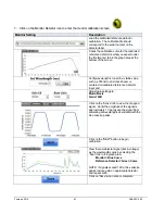
4. Click on the monochromator icon to adjust the scan range for the sample.
Monochromator Setting
Setting
Set scan range to the values shown to the
left.
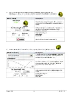
5. Click on Sample icon to enter the sample screen and adjust the following settings
Sample Setting
Description
Reading should be close to room temperature in
degrees C. Verify BNC cable is connected from sample
stage BNC to Temperature BNC on back panel.
1 = minimum average. Scan time = 8’ 30” good for
quick scan test
5 = low average for calibration. Scan time = 9’ 31”
10 = recommended for calibration. Scan time = 10’ 50”
40 = high accuracy calibration. Scan time = 18’ 30”
Set Bias Voltage = 0 for this PV sample measurement
using
a) enter “0” in bias voltage text box
b) click on “zero bias”
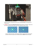
Verify input selection switch points to the BNC input port.
Verify BNC cable is connected from Calibrated Sample
Cell to BNC input on back panel.
If you can’t see the output, verify wavelength is set to a
visible value such as 555nm. Center beam on to
detector surface.
Enable Sample (calibrated reference detector) and verify
chopped signal is being plotted on the Active graph at
the bottom of the Sample Screen.
Adjust gain settings to:
Mode: Basic
Gain: 100K
NOTE: Changing the gain values on the sample will not
void the system calibration. This allows you to


