background image

Dirt Medic™  

ALWAYS wear safety goggles or protective eye-wear when operating the unit!


Dirt Medic™ Manual / 3315.1016 


Page 7 of 9 

PARTS LIST


Item 
Number 

Description 

Part 
Number


#1  

Wheel, 2 required 

10000129 

#2  

Right Wheel Arm  

10002614 

#3  

Left Wheel Arm  

10002613  

#4 

Wheel Arm Detent Pin, 2 required 

10002554 

#5 

Weight Tray 

10002607 

#6 

Scraper Blade Bar 

10004683 

#7  

Scraper Blade  

10002604 

#8 

Harrow Spike, 8 required  

10002315 

#9 

Harrow Spike Bar 

10004650  

#10 

Harrow Spike Brackets, 8 required 

10004649 

#11  

U-Bolts with Nuts, 8 required 

10002342 

#12 

Leading Bar 

10002602 

#13 

Tongue Hitch Pin, ½” x 3” 

10000314 

#14 

Split Ring, Tongue Hitch Pin 

10002567 

#15 

Tongue Nose Hitch Pin 

10002565 

#16 

Adjustable Link 

10002552 

#17 

5/8” x 3” Hitch Pin 

10000315 

#18 

Adjuster Shaft 

10004125 

#19 

Adjuster Shaft Nut 

10004126 

#20 

Tongue Nose 

10002587 

#21 

Tongue 

10002589 

#22 

Tongue Brace, 2 required 

10002591 

#23 

Tongue Yoke 

10002590 

#24 

Tongue Link 

10002588 

#25 

Hand Crank 

10002615 

#26 

Adjuster Shaft Bearing 

10003131 

#27 

Right Side Plate 

10004682 

#28 

Left Side Plate 

10004681 

#29 

Skid Pads, 2 required (Not Shown) 

10002583 

#30 

Brush Retainer 

10004686 

#31 

Brush Arm, Left 

10004684 

#32 

Brush Arm, Right 

10004685 

#33 

18” Outside Brush Segment, 2 required 

10001934 

#34 

24” Center Brush Segment 

10001935 

Summary of Contents for Dirt Medic

Page 1: ...Dirt Medic Manual 3315 1016 Rev1 Dirt Medic Product Manual ...

Page 2: ...ge 9 Thank you For your purchase of the Newstripe Dirt Medic Infield Drag Groomer Please read over the instructions and make sure you understand operating procedures before using the unit Please check the serial number on your unit This manual is for units with serial number 10015597 and above only For units with serial numbers below 10015596 please contact Newstripe for the correct manual ...

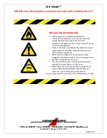
Page 3: ... death Always consult your Facility Safety and or Personnel Department for specified safety protocols prior to operating this equipment Make sure the wheel arm detent pins are fully engaged in the frame holes or serious damage to the groomer and operator can occur The unit will move when raising and lowering the wheels if not attached to a tow vehicle Wheel lift arms can move quickly with great fo...

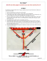
Page 4: ...1 4 Place one tongue brace on each side of the tongue Install each tongue brace between the tongue and leading bar with two 5 16 bolts four 5 16 flat washers and two 5 16 locking nuts Hand tighten only Pic 1 5 Securely tighten all six bolts washers and locking nuts Pic 1 6 Install the chrome handle on the crank at the end of the adjuster shaft with the 3 8 locking nut 7 Thread the adjuster shaft i...

Page 5: ...Dirt Medic ALWAYS wear safety goggles or protective eye wear when operating the unit Dirt Medic Manual 3315 1016 Page 3 of 9 Pic 2 Pic 3 ...

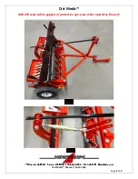
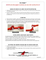
Page 6: ...he wheel arm back and down to lower the wheel and raise the unit Push the wheel arm pin into the top hole in the side of the frame tow position Repeat this procedure on other side and then lift the brush up to the stowed position Pic 4 ATTACHING THE UNIT TO A VEHICLE 1 Remove the hitch pin that is used to lock the tongue link and tongue to the tongue nose for towing 2 Raise tongue while rotating t...

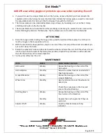
Page 7: ...n the down position if desired When the tongue is set to float you may stow the hitch pin in the unused upper hole at the rear of the tongue nose bar until it is needed CUTTING DEPTHS AND HEIGHT ADJUSTMENTS The Dirt Medic has been designed so that the scraper blade and harrow spike bar may be adjusted together or independently to allow for different surface and soil conditions Adjusting the scrape...

Page 8: ...ngue in the tow position Pic 4 2 With the brush in the down position step to one side of the unit and pull the wheel arm detent pin out until it clears the frame 3 Rotate the wheel arm back and down to lower the wheel and raise the unit Push the wheel arm pin into the top hole in the side of the frame tow position Repeat this procedure on other side and then lift the brush up to the stowed positio...

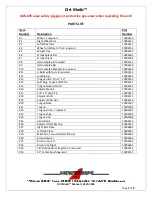
Page 9: ...red 10002342 12 Leading Bar 10002602 13 Tongue Hitch Pin x 3 10000314 14 Split Ring Tongue Hitch Pin 10002567 15 Tongue Nose Hitch Pin 10002565 16 Adjustable Link 10002552 17 5 8 x 3 Hitch Pin 10000315 18 Adjuster Shaft 10004125 19 Adjuster Shaft Nut 10004126 20 Tongue Nose 10002587 21 Tongue 10002589 22 Tongue Brace 2 required 10002591 23 Tongue Yoke 10002590 24 Tongue Link 10002588 25 Hand Crank...

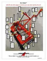
Page 10: ... Scraper Blade Bar 20 Tongue Nose 9 Harrow Spike Bar 10 11 Spike Brackets U Bolts 8 Harrow Spike 22 Tongue Brace 24 Tongue Link 15 Tongue Nose Hitch Pin 21 Tongue 16 Adjustable Link 18 Adjuster Shaft 28 Left Side Plate 23 Tongue Yoke 19 Adjuster Shaft Nut 26 Adjuster Shaft Bearing 27 Right Side Plate 31 Left Brush Arm 30 33 34 Brush Retainer Brush Segments 32 Right Brush Arm 17 Pin 13 14 Hitch Pin...

Page 11: ...s please visit www newstripe com terms of use privacy policy Components not manufactured by Newstripe Inc such as engines compressors pumps and transaxles are furnished with their respective manufacturer s warranties only Where Newstripe elects to extend manufacturers warranties the warranty shall cover up to 100 of the cost to repair or replace materials and parts for the first 12 months of owner...

Reviews: