NEWTON S
14
SYSTEM OPERATION MANUAL
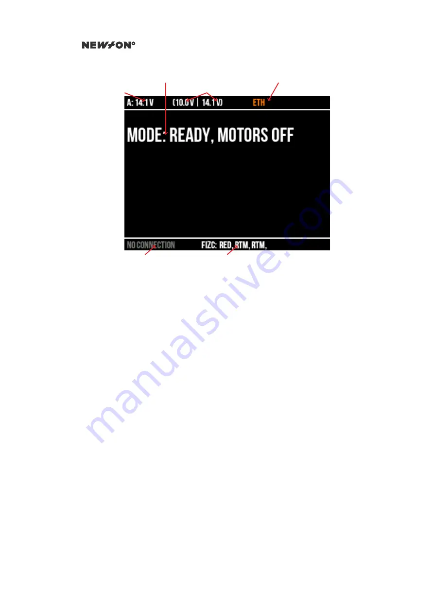
Supply voltage
Battery voltages
Mode indication
Communication interface
Controller
FIZC interfaces
Figure 4.2: Newton S2 Main Page
The top row shows:
1. Supply voltage (either battery or external)
2. Battery voltage for battery 1 and 2
3. Currently active communication link
Under this is a mode indicator. On startup this will show which calibration step is currently exe-
cuting, and after that what mode has been activated from the remote control. Together with the mode
indication is also an indication of any errors detected. If any error is shown, look at the troubleshooting
guide in chapter
.
The bottom row of the screen shows currently connected controller (the Dominion) and which
camera/lens (FIZC) interface dongles are currently connected and identified.
4.2
OPERATING THE HEAD
The Newton C1 controller is used for all normal operation controls of Newton S.
The main control for the remote head is provided by the joystick. The coupling between the three
axes of the joystick and the axes of the remote head depends on which control mode is selected, using
the mode switch (point 17).
0 - Motors off
All motors are off and the head is inactive
1 - Active - Roll Position
The head is active. Joystick left-right controls pan, up-down controls tilt
and rotating the joystick controls the roll of the remote head. A given rotation directly match a
given roll angle
2 - Active - Roll Fixed
The head is active. Joystick left-right controls pan and up-down controls tilt.
Roll of the remote head is locked to its current position
DO NOT DISTRIBUTE
Copyright © 2019 Newton Nordic AB


