


Copyright © 2023 NexCOBOT Co., Ltd. All Rights Reserved.
33
NEX 813 User Manual
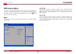
Chapter 3: BIOS Setup
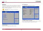
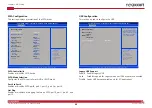
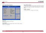
Digital IO Port Configuration
This section is used to configure digital I/O port settings.
DIO Port1 to DIO Port8
Configures DIO port1 to port8 as input or output.
Output Level
Configures the output level as high or low.
Advanced
Version 2.20.1271. Copyright (C) 2019 American Megatrends, Inc.
Aptio Setup Utility - Copyright (C) 2019 American Megatrends, Inc.
→←: Select Screen
↑↓: Select Item
Enter: Select
+/-: Change Opt.
F1: General Help
F2: Previous Values
F3: Optimized Defaults
F4: Save & Exit
ESC: Exit
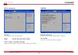
Set DIO as Input or Output
Digital IO Port Configuration
DIO Port1
Output Level
DIO Port2
Output Level
DIO Port3
Output Level
DIO Port4
Output Level
DIO Port5
DIO Port6
DIO Port7
DIO Port8
[Output]
[High ]
[Output]
[High ]
[Output]
[High ]
[Output]
[High ]
[Input ]
[Input ]
[Input ]
[Input ]
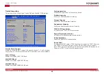
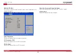
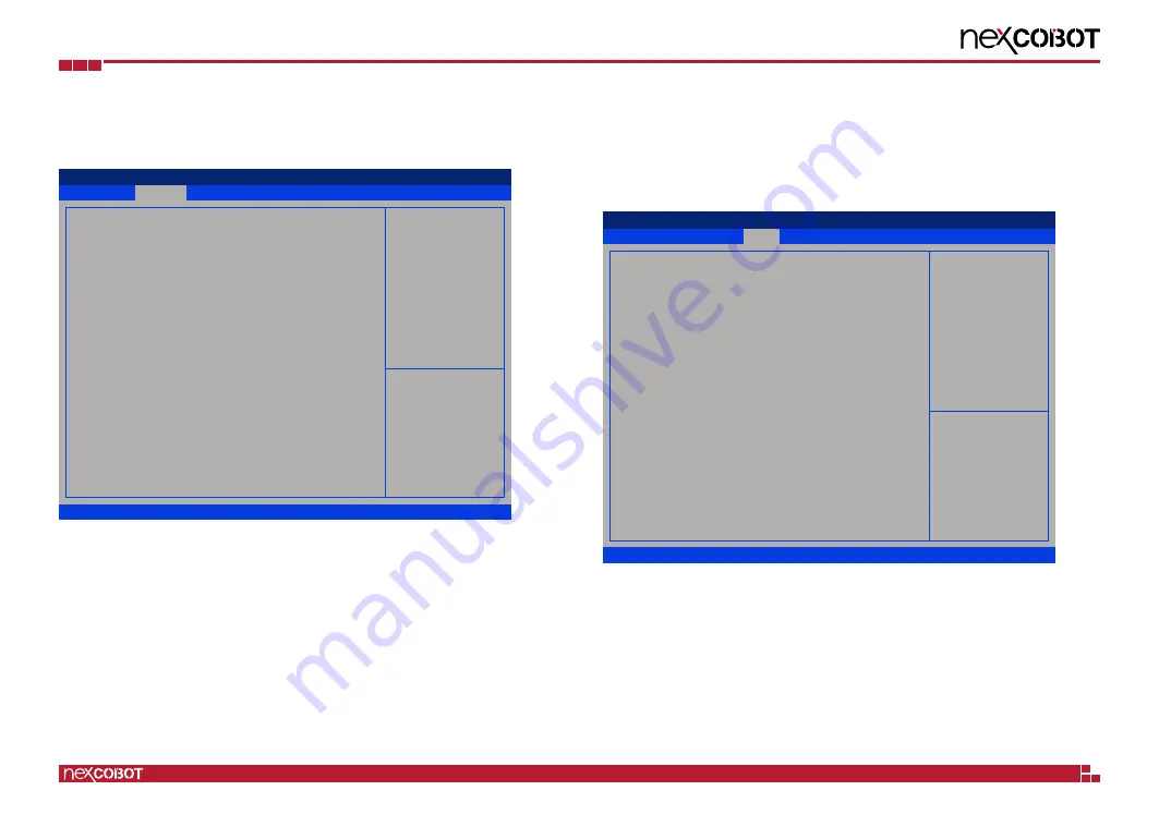
System Agent (SA) Configuration
Enters the System Agent (SA) Configuration submenu.
PCH-IO Configuration
Enters the PCH-IO Configuration submenu.
Chipset
This section gives you functions to configure the system based on the
specific features of the chipset. The chipset manages bus speeds and access
to system memory resources.
Save & Exit
Advanced
Chipset
Security
Boot
Main
Version 2.20.1271. Copyright (C) 2019 American Megatrends, Inc.
Aptio Setup Utility - Copyright (C) 2019 American Megatrends, Inc.
→←: Select Screen
↑↓: Select Item
Enter: Select
+/-: Change Opt.
F1: General Help
F2: Previous Values
F3: Optimized Defaults
F4: Save & Exit
ESC: Exit
System Agent (SA) Parameters
System Agent (SA) Configuration
PCH-IO Configuration
►
►


