background image

NEXCOM International Co., Ltd.

NEXCOM International Co., Ltd.

Published March 2019

www.nexcom.com

IoT Automation Solutions Business Group

Embedded Computing (3.5” CPU Board) 
EBC 357X

User Manual

Summary of Contents for EBC 357X Series

Page 1: ...NEXCOM International Co Ltd NEXCOM International Co Ltd Published March 2019 www nexcom com IoT Automation Solutions Business Group Embedded Computing 3 5 CPU Board EBC 357X User Manual ...

Page 2: ...er 1 Product Introduction Overview 1 Key Features 1 Hardware Specifications 2 Knowing Your EBC 357X 4 Top View 4 Bottom View 5 Edge I O View 6 Chapter 2 Jumpers and Connectors Before You Begin 7 Precautions 7 Jumper Settings 8 Locations of the Jumpers and Connectors 9 Jumpers 10 AT ATX Power Type Select 10 RTC Clear Select 10 LCD Power Select 11 PWM CCFL Select 11 Connector Pin Definitions 12 Exte...

Page 3: ...or 20 SIM Card Connector 20 SATA Connector A 21 SATA DOM Power Connector 21 M 2 Connector 22 Block Diagram 23 Chapter 3 BIOS Setup About BIOS Setup 24 When to Configure the BIOS 24 Default Configuration 25 Entering Setup 25 Legends 25 BIOS Setup Utility 27 Main 27 Advanced 28 Chipset 49 Security 66 Boot 66 Save Exit 67 Appendix A GPI O Programming Guide 69 Appendix B Watchdog Timer Setting 71 ...

Page 4: ...EXCOM International Co Ltd All other product names mentioned herein are registered trademarks of their respective owners Regulatory Compliance Statements This section provides the FCC compliance statement for Class A devices and describes how to keep the system CE compliant Declaration of Conformity FCC This equipment has been tested and verified to comply with the limits for a Class A digital dev...

Page 5: ... Polybrominated diphenyl Ethers PBDE 0 1 or 1 000ppm In order to meet the RoHS compliant directives NEXCOM has established an engineering and manufacturing task force in to implement the introduction of green products The task force will ensure that we follow the standard NEXCOM development procedure and that all the new RoHS components and new manufacturing processes maintain the highest industry...

Page 6: ...ective products making sure it is durable enough to be resistant against further damage and deterioration during transportation In case of damages occurred during transportation the repair is treated as Out of Warranty Any products returned by NEXCOM to other locations besides the customers site will bear an extra charge and will be billed to the customer Repair Service Charges for Out of Warranty...

Page 7: ...nd power supply are inconsistent with these instructions or the instructions for accessory modules contact the supplier to find out how you can ensure that your computer meets safety and regulatory requirements Cautions Electrostatic discharge ESD can damage system components Do the described procedures only at an ESD workstation If no such station is available you can provide some ESD protection ...

Page 8: ...e the soft metal or plastic parts of the connectors Safety Information Before installing and using the device note the following precautions Read all instructions carefully Do not place the unit on an unstable surface cart or stand Follow all warnings and cautions in this manual When replacing parts ensure that your service technician uses parts specified by the manufacturer Avoid using the system...

Page 9: ...ket must be located near the equipment and must be easily accessible 6 Keep the board away from humidity 7 Put the board on a stable surface Dropping it or letting it fall may cause damage 8 Wear anti static wrist strap 9 Do all preparation work on a static free surface 10 Make sure the voltage of the power source is correct before connecting the equipment to the power outlet 11 Hold the board onl...

Page 10: ...ion of the installed software operating system version application software etc A complete description of the problem The exact wordings of the error messages Warning 1 Handling the unit carry the unit with both hands and handle it with care 2 Maintenance to keep the unit clean use only approved cleaning products or clean with a dry cloth Conventions Used in this Manual Warning Information about c...

Page 11: ...hung Office 16F No 250 Sec 2 Chongde Rd Beitun Dist Taichung City 406 R O C Tel 886 4 2249 1179 Fax 886 4 2249 1172 Email sales nexcom com tw www nexcom com tw NexCOBOT Taiwan Co Ltd 13F No 916 Chung Cheng Rd ZhongHe District New Taipei City 23586 Taiwan R O C Tel 886 2 8226 7796 Fax 886 2 8226 7792 Email sales nexcom com tw www nexcom com tw GreenBase Technology Corp 13F No 922 Chung Cheng Rd Zho...

Page 12: ...mingzun Plaza Bldg 1 No 609 Yunlin East Rd Shanghai 200062 China Tel 86 21 5278 5868 Fax 86 21 3251 6358 Email sales nexcom cn www nexcom cn NEXCOM Surveillance Technology Corp Floor 5 Building C ZhenHan Industrial Zone GanKeng Community Buji Street LongGang District ShenZhen 518112 China Tel 86 755 8364 7768 Fax 86 755 8364 7738 Email steveyang nexcom com tw www nexcom cn NEXCOM United System Ser...

Page 13: ... received is complete Your package should have all the items listed in the following table Item Name Qty 1 EBC 357X Motherboard 1 Optional Accessories Item Part Number Name Description 1 60233SIO62X00 COM Port Cable CP NEX 110819 01 UL2651 28x9C DB9 TU1001 10 L 200mm 2 60233AT136X00 7P 15P SATA Cable SATA Cable ST MD 6101098 SATA 22P F to SATA 7P F 90 degree 2P H S L 300mm ...

Page 14: ...0X0 RoHS Compliant Low power embedded board with Intel Atom processor E3950 and extended 20 C 60 C with HDMI VGA LVDS 2 x USB 3 0 4 x USB 2 0 2 x COMs 1 x M 2 B key 2 x Gigabit LANs 1 x SATA EBC 357X E3930 P N 10E00035701X0 RoHS Compliant Low power embedded board with Intel Atom processor E3930 and extended 20 C 60 C with HDMI VGA LVDS 2 x USB 3 0 4 x USB 2 0 2 x COMs 1 x M 2 B key 2 x Gigabit LAN...

Page 15: ...n board Intel Atom processor E39xx processor family CPU upside down design 2 x 204 pin SO DIMM DDR3L Triple display HDMI VGA LVDS 1 x M 2 2242 B key 2 x Intel i210 IT PCI Express Gigabit Ethernet 1 x SATA 2 0 2 x USB 3 0 4 x USB 2 0 4 in 4 out GPIO Mic in Speaker out Serial port 1 x RS232 1 x RS232 422 485 port Support AT ATX mode and single 12VDC input Overview ...

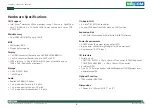
Page 16: ... 2242 B key 1 x SATA port Audio Realtek ALC888s HD Codec 1 x 4 pin header for mic in 2 0 pitch 1 x 4 pin header for line out 2 0 pitch 1 x 5 pin header for speaker out 2 0 pitch On board LAN 2 x Intel I210 IT GbE controller Support PXE boot from LAN wake on LAN function Expansion Slot 1 x M 2 slot M key supports PCIe default SATA interface Power Requirements AT ATX mode By jumper setting default A...

Page 17: ...ghts Reserved 3 EBC 357X User Manual Chapter 1 Product Introduction Environment Board level operating temperatures 20 C to 60 C Relative Humidity 10 to 90 operating non condensing 5 to 95 non operating non condensing Certifications Meet CE FCC Class A ...

Page 18: ...C 357X User Manual Chapter 1 Product Introduction Knowing Your EBC 357X Top View SATA LVDS Panel Inverter LCD PWR Select PWN CCFL Select M 2 SATA DOM Power COM1 COM2 GPIO Mic in Power Button ATX LED SMBus Reset RTC Clear Speaker out Line out 12V DC Input AT ATX Select ...

Page 19: ...Copyright 2016 NEXCOM International Co Ltd All Rights Reserved 5 EBC 357X User Manual Chapter 1 Product Introduction Bottom View SIM Card ...

Page 20: ...Copyright 2016 NEXCOM International Co Ltd All Rights Reserved 6 EBC 357X User Manual Chapter 1 Product Introduction Edge I O View HDMI LAN1 USB 2 0 USB 3 0 VGA LAN2 ...

Page 21: ...rself before touching any internal components by touching a metal object Static electricity can damage many of the electronic components Humid environments tend to have less static electricity than dry environments A grounding strap is warranted whenever danger of static electricity exists Precautions Computer components and electronic circuit boards can be damaged by discharges of static electric...

Page 22: ... jumpers ensure that the jumper caps are placed on the correct pins When the jumper cap is placed on both pins the jumper is short If you remove the jumper cap or place the jumper cap on just one pin the jumper is open Refer to the illustrations below for examples of what the 2 pin and 3 pin jumpers look like when they are short on and open off Two Pin Jumpers Open Left and Short Right Three Pin J...

Page 23: ...9 EBC 357X User Manual Chapter 2 Jumpers and Connectors Locations of the Jumpers and Connectors The figure below shows the location of the jumpers and connectors J1 JP1 JP2 VGA1 CN8 USB2 USB1 LAN1 LAN2 J9 J10 JP6 J6 J4 JP5 CN9 JP4 JP3 CN6 CN3 CON2 J2 JP10 JP11 CN4 ...

Page 24: ... AT ATX Power Type Select Connector type 1x3 3 pin header 2 0mm pitch Connector location JP3 Pin Definition 1 ATX_PWRBT 2 PWRBTN 3 AT_PWRBT 1 3 1 3 JP10 Pin Definition 1 NC 2 S_RTC_RST 3 GND JP11 Pin Definition 1 NC 2 S_RTC_TEST 3 GND RTC Clear Select Connector type 1x3 3 pin header 2 0mm pitch Connector location JP10 and JP11 ...

Page 25: ...s Pin Settings 1 2 On VCC3 2 3 On VCC5 1 2 On default Pin Definition 1 3V3 2 VCCLCDIN 3 5V Pin Definition 1 CCFLBKLTCTRL 2 PL_BKLTCTRL 3 PWM_CTRL LCD Power Select Connector type 1x3 3 pin header 2 0mm pitch Connector location JP2 PWM CCFL Select Connector type 1x3 3 pin header 2 0mm pitch Connector location JP1 1 3 1 3 ...

Page 26: ...A_BLUE_C 4 NC 5 GND 6 GND 7 GND 8 GND 9 5V_VGA 10 GND 11 NC 12 VGA_DDCDATA_C 13 VGA_HSYNC_C 14 VGA_VSYNC_C 15 VGA_DDCCLK_C 5 15 11 1 Pin Definition Pin Definition 1 HDMI_DATA2_P_C 2 GND 3 HDMI_DATA2_N_C 4 HDMI_DATA1_P_C 5 GND 6 HDMI_DATA1_N_C 7 HDMI_DATA0_P_C 8 GND 9 HDMI_DATA0_N_C 10 HDMI_CLK_P_C 11 GND 12 HDMI_CLK_N_C 13 NC 14 NC 15 HDMI_CTRL_CLK_C 16 HDMI_CTRL_DATA_C 17 GND 18 HDMI_5V 19 HDMI_H...

Page 27: ...al USB 3 0 port Connector location USB1 Pin Definition Pin Definition 1 P5V_OC01_C 2 USB_0N_C 3 USB_0P_C 4 GND 5 P5V_OC01_C 6 USB_1N_C 7 USB_1N_C 8 GND Pin Definition Pin Definition 1 P5V_OC23_C 2 USB_2N_C 3 USB_2P_C 4 GND 5 USB3_RX2_N_C 6 USB3_RX2_P_C 7 GND 8 USB3_TX2_N_C 9 USB3_TX2_P_C 10 P5V_OC23_C 11 USB_3N_C 12 USB_3P_C 13 GND 14 USB3_RX3_N_C 15 USB3_RX3_P_C 16 GND 17 USB3_TX3_N_C 18 USB3_TX3...

Page 28: ... MDI_3_P_1 10 MDI_3_N_1 11 LED0_1 12 LED2_1 13 LED1_1 14 3VSB Pin Definition Pin Definition 1 MDI_0_P_2 2 MDI_0_N_2 3 MDI_1_P_2 4 MDI_1_N_2 5 1V5_LAN2 6 GND 7 MDI_2_P_2 8 MDI_2_N_2 9 MDI_3_P_2 10 MDI_3_N_2 11 LED0_2 12 LED2_2 13 LED1_2 14 3VSB ACT LINK 8 1 ACT LINK 8 1 Act Status Flashing Yellow Data activity Off No activity Link Status Steady Green 1G network link Steady Orange 100Mbps network li...

Page 29: ...nnector type 2x2 Aux power connector Connector location CON2 Pin Definition 1 GND 2 GND 3 12V 4 12V 1 2 3 4 Power Button LED SMBus Reset Connector type 2x7 14 pin header 2 0mm pitch Connector location JP4 1 13 2 14 Pin Definition Pin Definition 1 PWRLEDP 2 3V3 3 HDDLEDP 4 3V3 5 S_SMB_CLK 6 3V3 7 S_SMB_DATA 8 GND 9 S_SLP_S3 10 PS_ON 11 RSTBTN 12 GND 13 ATX_PWRBT 14 GND ...

Page 30: ...ocation JP5 1 9 2 10 Pin Definition Pin Definition 1 5V_IO 2 GND 3 ICH_GPO0_OUT 4 ICH_GPI0_IN 5 ICH_GPO1_OUT 6 ICH_GPI1_IN 7 ICH_GPO2_OUT 8 ICH_GPI2_IN 9 ICH_GPO3_OUT 10 ICH_GPI3_IN COM Port 1 RS232 Connector type 1x10 10 pin header 1 0mm pitch Connector location J6 Pin Definition Pin Definition 1 SP1_DCD 2 SP1_RXD 3 SP1_TXD 4 SP1_DTR 5 GND 6 SP1_DSR 7 SP1_RTS 8 SP1_CTS 9 SP1_RI 10 GND 10 1 ...

Page 31: ...S485 Connector type 1x10 10 pin header 1 0mm pitch Connector location J4 Pin Definition Pin Definition 1 SP2_DCD 2 SP2_RXD 3 SP2_TXD 4 SP2_DTR 5 GND 6 SP2_DSR 7 SP2_RTS 8 SP2_CTS 9 SP2_RI 10 GND 10 1 Mic in Connector Connector type 1x4 4 pin header 2 0mm pitch Connector location J10 Pin Definition 1 MIC1 L3_C 2 MIC_GND 3 MIC1_JD 4 MIC1 R3_C 1 4 ...

Page 32: ...e out Connector Connector type 1x4 4 pin header 2 0mm pitch Connector location J9 Pin Definition 1 HP_OUTL_R2 2 GND 3 LINE2_JD 4 HP_OUTR_R2 1 4 Speaker out Connector Connector type 1x5 5 pin header 2 0mm pitch Connector location JP6 1 5 Pin Definition Pin Definition 1 LOUT_P_R_C 2 LOUT_N_R_C 3 GND 4 ROUT_P_R_C 5 ROUT_N_R_C ...

Page 33: ... LVDS_DDC_CLK 2 LVDS_DDC_DATA 3 VCC_LCD 4 LVDSA_LDC0P 5 LVDSA_LDC3P 6 LVDSA_LDC0N 7 LVDSA_LDC3N 8 VCC_LCD 9 GND 10 LVDSA_LDC1P 11 LVDSA_LL1CP 12 LVDSA_LDC1N 13 LVDSA_LL1CN 14 GND 15 GND 16 V_INV 17 LVDSA_LDC2P 18 V_INV 19 LVDSA_LDC2N 20 GND Pin Definition Pin Definition 1 LVDS_DDC_CLK 2 LVDS_DDC_DATA 3 VCC_LCD 4 LVDSA_LDC4P 5 LVDSB_LDC7P 6 LVDSA_LDC4N 7 LVDSA_LDC7N 8 VCC_LCD 9 GND 10 LVDSA_LDC5P 1...

Page 34: ... Connector type 1x7 7 pin header JST 2 0mm pitch Connector location J1 Pin Definition Pin Definition 1 5V 2 V_INV 3 V_INV 4 PL_BKLTCTRL 5 GND 6 GND 7 M_BKLTEN_R 7 1 SIM Card Connector Connector type SIM card slot Connector location IDE1 C5 C6 C7 C1 C2 C3 Pin Definition Pin Definition C1 UIM_PWER C2 UIM_REST C3 UIM_CLK C5 GND C6 UIM_PWER C7 UIM_DATA ...

Page 35: ...onnector A Connector type Standard Serial ATA 7P 1 27mm SATA M 180 Connector location CN3 1 7 Pin Definition Pin Definition 1 GND 2 SATA_TXP0_C 3 SATA_TXN0_C 4 GND 5 SATA_RXN0_C 6 SATA_RXP0_C 7 GND SATA DOM Power Connector Connector type 1x2 JST 2 pin header 2 5mm pitch Connector location J2 Pin Definition 1 5V_SATA 2 GND 1 2 ...

Page 36: ...F_WWAN_GPS_ON 27 GND 28 NC 29 USB3_RX0_N_C 30 UIM_REST 31 USB3_RX0_P_C 32 UIM_CLK 33 GND 34 UIM_DATA 35 USB3_TX0_N_C 36 UIM_PWER 37 USB3_TX0_P_C 38 SATA_DEVSLP1 Pin Definition Pin Definition 39 GND 40 NC 41 NGFF_PE_SSD_RXP1 42 NC 43 NGFF_PE_SSD_RXN1 44 NC 45 GND 46 NC 47 NGFF_PE_SSD_TXN1 48 NC 49 NGFF_PE_SSD_TXP1 50 NGFF_PERSET 51 GND 52 NC 53 NGFF_CLK_N_C 54 NGFF_WAKE 55 NGFF_CLK_P_C 56 NGFF_SMB_...

Page 37: ...z LVDSSingleChannel 18 24bit DP SATA Con x 1 VGA CON 1920x1200 60Hz PCIe 0 M 2 B Key 3G PCIe 1 Intel I210 LAN1 1 x 5 Pin Header 1 x 4 Pin Header 1 x 4 Pin Header Intel I210 PCIe 2 LAN2 SIM Card COM2 RS232 422 485 COM1 3 4 RS232 Debug Port TPM Module USB 3 0 CONN USB 2 0 CONN USB 2 0 Pin Header ITE8786 GPIO IN 4 OUT 4 1333 1600 1867 SO DIMM0 address A0 1333 1600 1867 SO DIMM0 address A2 SATA 0v USB...

Page 38: ...s configured with the values found in CMOS With easy to use pull down menus you can configure such items as Hard drives diskette drives and peripherals Video display type and display options Password protection from unauthorized use Power management features The settings made in the setup program affect how the computer performs It is important therefore first to try to understand all the setup op...

Page 39: ...l be reported in one of two different ways If the error occurs before the display device is initialized a series of beeps will be transmitted If the error occurs after the display device is initialized the screen will display the error message Powering on the computer and immediately pressing Del allows you to enter Setup Press the key to enter Setup Legends Key Function Moves the highlight left o...

Page 40: ...up screen it indicates that there are more available fields not shown on the screen Use the up and down arrow keys to scroll through all the available fields Submenu When appears on the left of a particular field it indicates that a submenu which contains additional options are available for that field To display the submenu move the highlight to that field and press ...

Page 41: ...15 24 Administrator B2 0 56 1A 03 22 3 0 1 1107 4 0 10 3351 10 0 1033 BXT Notebook Desktop Oxbow Hill CRB 06 FAB A 8192 MB 1600 MHz System Language Selects the language of the system System Date The date format is day month date year Day displays a day from Monday to Sunday Month displays the month from January to December Date displays the date from 1 to 31 Year displays the year from 1999 to 209...

Page 42: ... ACPI Settings IT8786 Super IO Configuration Hardware Monitor CPU Configuration AMI Graphic Output Protocol Policy Network Stack Configuration CSM Configuration USB Configuration Platform Trust Technology Security Configuration Thermal System Component Debug Configuration RC ACPI Settings RTD3 settings Intel R I210 Gigabit Network Connection NIC1 This section is used to configure network settings ...

Page 43: ... Exit ESC Exit Intel R I210 Gigabit Network Connection NIC2 This section is used to configure network settings of the LAN controller NIC Configuration Enters the network configuration sub menu of the network controller Exit Advanced Chipset PCIPnP Security Main Version 2 18 1260 Copyright C 2016 American Megatrends Inc Aptio Setup Utility Copyright C 2016 American Megatrends Inc Click to configure...

Page 44: ... Exit ESC Exit Intel R I210 Gigabit Network Connection NIC2 This section is used to configure network settings of the LAN controller NIC Configuration Enters the network configuration sub menu of the network controller Exit Advanced Chipset PCIPnP Security Main Version 2 18 1260 Copyright C 2016 American Megatrends Inc Aptio Setup Utility Copyright C 2016 American Megatrends Inc Click to configure...

Page 45: ...ovides Health Status for the Drivers Controllers Intel R PRO 1000 7 1 07 PCI E Healthy Select Screen Select Item Enter Select Change Opt F1 General Help F2 Previous Values F3 Optimized Defaults F4 Save Exit ESC Exit Exit Advanced Chipset PCIPnP Security Main Version 2 18 1260 Copyright C 2016 American Megatrends Inc Aptio Setup Utility Copyright C 2016 American Megatrends Inc Provides Health Statu...

Page 46: ...is pressed Lock Legacy Resources Enables or disables system ability to prevent the operating system from modifying assignments for legacy resources serial parallel and PS 2 ports Select Screen Select Item Enter Select Change Opt F1 General Help F2 Previous Values F3 Optimized Defaults F4 Save Exit ESC Exit Trusted Computing This section is used to configure Trusted Platform Module TPM settings Adv...

Page 47: ...uper IO Configuration Super IO Chip Serial Port 1 Configuration Serial Port 2 Configuration Serial Port 3 Configuration Serial Port 4 Configuration Serial Port 5 Configuration IT8786 Serial Port 1 Configuration This section is used to configure serial port 1 Serial Port Enables or disables the serial port Change Settings Selects an optimal setting for the Super IO device Advanced Version 2 18 1260...

Page 48: ...p F2 Previous Values F3 Optimized Defaults F4 Save Exit ESC Exit Enable or Disable Serial Port COM Serial Port 2 Configuration Serial Port Device Settings Serial Port Mode Terminal 120 Ohm Change Settings Enabled IO 2F8h IRQ 3 RS232 Disabled IO 2F8h IRQ 3 Serial Port 3 Configuration This section is used to configure serial port 3 Serial Port Enables or disables the serial port Change Settings Sele...

Page 49: ...n Megatrends Inc Aptio Setup Utility Copyright C 2016 American Megatrends Inc Select Screen Select Item Enter Select Change Opt F1 General Help F2 Previous Values F3 Optimized Defaults F4 Save Exit ESC Exit Enable or Disable Serial Port COM Serial Port 4 Configuration Serial Port Device Settings Change Settings Enabled IO 2E8h IRQ 10 IO 2E8h IRQ 10 Advanced Version 2 18 1260 Copyright C 2016 Ameri...

Page 50: ... 12V 5V 33 C 27 C N A 0 900 V 3 284 V 12 024 V 5 100 V CPU Configuration This section is used to configure the CPU settings Advanced Version 2 18 1260 Copyright C 2016 American Megatrends Inc Aptio Setup Utility Copyright C 2016 American Megatrends Inc Select Screen Select Item Enter Select Change Opt F1 General Help F2 Previous Values F3 Optimized Defaults F4 Save Exit ESC Exit Socket specific CP...

Page 51: ...PU Information Display information on the CPU installed on socket 0 Advanced Version 2 18 1260 Copyright C 2016 American Megatrends Inc Aptio Setup Utility Copyright C 2016 American Megatrends Inc Select Screen Select Item Enter Select Change Opt F1 General Help F2 Previous Values F3 Optimized Defaults F4 Save Exit ESC Exit Socket 0 CPU Information Intel R Atom TM Processor E3950 1 60GHz CPU Signa...

Page 52: ...onfigures which display output to use upon boot CPU Power Management This section is used to configure the CPU power management settings Advanced Version 2 18 1260 Copyright C 2016 American Megatrends Inc Aptio Setup Utility Copyright C 2016 American Megatrends Inc Select Screen Select Item Enter Select Change Opt F1 General Help F2 Previous Values F3 Optimized Defaults F4 Save Exit ESC Exit Enabl...

Page 53: ... Stack Network Stack Disabled Advanced Version 2 18 1260 Copyright C 2016 American Megatrends Inc Aptio Setup Utility Copyright C 2016 American Megatrends Inc Select Screen Select Item Enter Select Change Opt F1 General Help F2 Previous Values F3 Optimized Defaults F4 Save Exit ESC Exit Enable Disable CSM Support Compatibility Support Module Configuration CSM Support Disabled Network Stack Enables...

Page 54: ... Device reset time out Device power up delay 16 Enabled Enabled Enabled 20 sec 20 sec Auto Legacy USB Support Enable Enables Legacy USB Auto Disables support for Legacy when no USB devices are connected Disable Keeps USB devices available only for EFI applications XHCI Hand off This is a workaround for OSs that does not support XHCI hand off The XHCI ownership change should be claimed by the XHCI ...

Page 55: ...ed Version 2 18 1260 Copyright C 2016 American Megatrends Inc Aptio Setup Utility Copyright C 2016 American Megatrends Inc Select Screen Select Item Enter Select Change Opt F1 General Help F2 Previous Values F3 Optimized Defaults F4 Save Exit ESC Exit TXE HMRFPO TXE EOP Message Disabled Enabled Platform Trust Technology This section is used to configure TPM settings Security Configuration This sec...

Page 56: ... 95 C 60 C Disable Thermal This section is used to configure thermal settings Automatic Thermal Reporting This item is used to configure _CRT _PSV and _AC0 automatically based on values recommended in BWG s Thermal Reporting for Thermal Management settings Set to Disabled for manual configuration Critical Trip Point This item is used to control the temperature of the ACPI Critical Trip Point the p...

Page 57: ...ystem Component This section is used to configure system component settings CRID Setting Configures the Revision ID reflected in PCI config space PMIC ACPI OBJECT Enables or disables PMIC ACPI device PNP Setting Configures the mode of PnP The options are Disable Performance Power and Power Performance OS Reset Select Configures the OS reset type The options are Warm Reset and Cold Reset Embedded P...

Page 58: ...ght C 2016 American Megatrends Inc Select Screen Select Item Enter Select Change Opt F1 General Help F2 Previous Values F3 Optimized Defaults F4 Save Exit ESC Exit NPK Debug Configuration TXE Debug Option End Of Post Lock Directory PTT Debug Option Suppress PTT Commands TDO GPIO Pin Switch TDO GPIO Pin Max Memory 2G Persistent RAM size OS DNX OS DnX focus entry ISH GPIO I2C0 Pull Up ISH GPIO I2C1 ...

Page 59: ...sor trace memory region size from 4KB to 128MB North Peak Enable Enables or disables north peak function FW Trace Enable Enables or disables FW trace function FW Trace Destination Configures the destination of FW trace NPK Recovery DUMP Enables or disables the NPK recovery dump feature Advanced Version 2 18 1260 Copyright C 2016 American Megatrends Inc Aptio Setup Utility Copyright C 2016 American...

Page 60: ...n Megatrends Inc Aptio Setup Utility Copyright C 2016 American Megatrends Inc Select Screen Select Item Enter Select Change Opt F1 General Help F2 Previous Values F3 Optimized Defaults F4 Save Exit ESC Exit Enable Disable Ready Mode support based on Windows Away mode Only on DT AIO Intel Ready Mode Technology Low Power S0 Idle Capability EC Notification PEP Constraints Configuration Disabled Disab...

Page 61: ...erican Megatrends Inc Select Screen Select Item Enter Select Change Opt F1 General Help F2 Previous Values F3 Optimized Defaults F4 Save Exit ESC Exit Add SDXC in PEP mitigation list PEP CPU PEP Graphics PEP SATA PEP UART PEP SDI0 PEP I2C0 PEP I2C1 PEP I2C2 PEP I2C3 PEP I2C4 PEP I2C5 PEP I2C6 PEP I2C7 PEP PWM1 PEP HSUART1 PEP HSUART2 PEP HSUART3 PEP HSUART4 PEP SPI1 PEP SPI2 PEP SPI3 PEP XHCI PEP ...

Page 62: ...d Disabled Disabled Enabled Disabled Disabled Disabled Disabled 3 3DX MiniCard RTD3 Settings This section is used to configure RTD3 settings RTD3 Support Enables or disables runtime D3 support Consolidated Power Resource Enables or disables 1 power resource for all power gated devices except the network device Use this for Modern Standby test P state Capping Enables or disables _PPC and the sendin...

Page 63: ...an Megatrends Inc Select Screen Select Item Enter Select Change Opt F1 General Help F2 Previous Values F3 Optimized Defaults F4 Save Exit ESC Exit Maximum Value of TOLUD Memory Information Total Memory Memory Slot0 Memory Slot1 Max TOLUD 8192 MB LPDDR3 4096 MB LPDDR3 4096 MB LPDDR3 2 GB Save Exit Advanced Chipset Security Boot Main Version 2 18 1260 Copyright C 2016 American Megatrends Inc Aptio S...

Page 64: ... Copyright C 2016 American Megatrends Inc Select Screen Select Item Enter Select Change Opt F1 General Help F2 Previous Values F3 Optimized Defaults F4 Save Exit ESC Exit Enable GOP Driver will unload VBIOS Disable it will load VBIOS GOP Configuration GOP Driver Intel Graphics Pei Display Peim GOP Brightness Level VBT Select IGD Configuration Integrated Graphics Device Primary Display RC6 Render S...

Page 65: ... PAVP BIA Configures the BIA level The options are Auto Disabled and Level 1 to Level 5 ALS Support Enables or disables ALS support Only valid for ACPI IGD Flat Panel Configures the resolution of the IGD flat panel IGD Boot Type Configures the display interface to use for the integrated graphics device when system boots Advanced Version 2 18 1260 Copyright C 2016 American Megatrends Inc Aptio Setu...

Page 66: ...es the IPU device Save Exit Advanced Chipset Security Boot Main Version 2 18 1260 Copyright C 2016 American Megatrends Inc Aptio Setup Utility Copyright C 2016 American Megatrends Inc Select Screen Select Item Enter Select Change Opt F1 General Help F2 Previous Values F3 Optimized Defaults F4 Save Exit ESC Exit HD Audio Configuration Settings HD Audio Configuration GMM Configuration ISH Configurat...

Page 67: ...io DSP HD Audio CSME Memory Transfers HD Audio Host Memory Transfers HD Audio I O Buffer Ownership Sele HD Audio BIOS Config Lock Down HD Audio Clock Gating HD Audio Power Gating HD Audio PME HD Audio Link Frequency iDisplay Link Frequency Enable Disable VC0 VC0 I2S port owns all t Enable Enable Enable Enable 24 MHz 96 MHz HD Audio Configuration HD Audio I O Buffer Ownership Select Configures the ...

Page 68: ...nd Clock Tr GMM Clock Gate Sideband Clock Pa GMM Clock Gate Core GMM Clock Gate DMA Engine GMM Clock Gate Register Access GMM Clock Gate Host Interface GMM Clock Gate Partition GMM Clock Gate Trunk GMM Power Gating Configuration GMM Power Gate HW Autonomous GMM Power Gate D3 Hot GMM Power Gate I3 Hot GMM Power Gate PMC Request Disable Enable Enable Enable Enable Enable Enable Enable Enable Enable ...

Page 69: ...dvanced Chipset Security Boot Main Version 2 18 1260 Copyright C 2016 American Megatrends Inc Aptio Setup Utility Copyright C 2016 American Megatrends Inc Select Screen Select Item Enter Select Change Opt F1 General Help F2 Previous Values F3 Optimized Defaults F4 Save Exit ESC Exit Enable Disable LPSS I2C 1 Support Low Power Sub System LPSS I2C 1 Support D22 F0 LPSS I2C 2 Support D22 F1 LPSS I2C ...

Page 70: ... Select Screen Select Item Enter Select Change Opt F1 General Help F2 Previous Values F3 Optimized Defaults F4 Save Exit ESC Exit Auto will make selection based on BoardID LPSS HSUART 4 Support D24 F3 LPSS SPI 1 Support D25 F0 LPSS SPI 2 Support D25 F1 LPSS SPI 3 Support D25 F2 NFC Selection GNSS GPS Mode Selection LPSS IOSF PMCTL S0ix Enable LPSS Clock Gating Configuration LPSS I2C 1 Clock Gating...

Page 71: ...ends Inc Aptio Setup Utility Copyright C 2016 American Megatrends Inc Select Screen Select Item Enter Select Change Opt F1 General Help F2 Previous Values F3 Optimized Defaults F4 Save Exit ESC Exit Select Screen Select Item Enter Select Change Opt F1 General Help F2 Previous Values F3 Optimized Defaults F4 Save Exit ESC Exit PCI Express Clock Gating Enable Disable for each root port Control the P...

Page 72: ... disables Root PCI Express System Error on Correctable Error PME SCI Enables or disables PCI Express PME SCI Save Exit Advanced Chipset Security Boot Main Version 2 18 1260 Copyright C 2016 American Megatrends Inc Aptio Setup Utility Copyright C 2016 American Megatrends Inc Select Screen Select Item Enter Select Change Opt F1 General Help F2 Previous Values F3 Optimized Defaults F4 Save Exit ESC E...

Page 73: ...selects the level of de emphasis for an upstream component 1b 3 5 dB 0b 6 dB Save Exit Advanced Chipset Security Boot Main Version 2 18 1260 Copyright C 2016 American Megatrends Inc Aptio Setup Utility Copyright C 2016 American Megatrends Inc Select Screen Select Item Enter Select Change Opt F1 General Help F2 Previous Values F3 Optimized Defaults F4 Save Exit ESC Exit When the Link is operating a...

Page 74: ...creen Select Item Enter Select Change Opt F1 General Help F2 Previous Values F3 Optimized Defaults F4 Save Exit ESC Exit Enables or Disables the Chipset SATA Controller The Chipset SATA controller supports the 2 black internal SATA ports up to 3Gb s supported per port SATA Port 0 Software Preserve Port 0 SATA Port 0 Hot Plug Capability Configured as eSATA Mechanical Presence Switch Spin Up Device ...

Page 75: ...nd port 1 Mechanical Presence Switch Enables or disables reporting of whether port 0 and port 1 have a mechanical presence switch Note Requires hardware support Spin Up Device Enables or disables staggered spin up on devices connected to SATA port 0 and port 1 SATA Port 0 and Port 1 DevSlp Enables or disables SATA port 0 and port 1 DevSlp Before enabling DevSlp board rework is needed DIT0 Configur...

Page 76: ...Change Opt F1 General Help F2 Previous Values F3 Optimized Defaults F4 Save Exit ESC Exit Enable Disable SCC SD Card Support SCC SD Card Support D27 F0 SCC eMMC Support D28 F0 eMMC Max Speed SCC UFS Support D29 F0 SCC SDIO Support D30 F0 Disable Enable HS400 Disable Disable SCC SD Card Support D27 F0 Enables or disables SCC SD card support SCC eMMC Support D28 F0 Enables or disables SCC eMMC suppo...

Page 77: ...sable FALSE Disable XHCI Pre Boot Driver Enables or disables XHCI Pre Boot driver support xHCI Mode Enables or disables XHCI mode Once disabled XHCI controller function will be disabled and all the USB devices will not be detectable and usable during boot up and in OS Please do not disable it unless for debugging purposes USB VBUS Enables or disables USB VBUS Please set VBUS to ON in HOST mode and...

Page 78: ... NFC Device NXP1001 Setting PSS Device IMPJ0003 Setting GPS Device BCM4752 Setting Fingerprint Sensor Touch Panel Device ELAN221D High Precision Timer 8254 Clock Gating State After G3 Power Button Debounce Mode Board Clock Spread Spectrum UART Interface Selection Wake On LAN BIOS Lock RTC Lock Flash Protection Range Registers TCO Lock DCI enable HDCIEN DCI Auto Detect Enable GPIO Lock LPSS Devices...

Page 79: ... be enabling the DCI feature DCI Auto Detect Enable Enables or disables DCI auto detection When enabled DCI will be activated and detection for DCI being connected will be initiated during BIOS post GPIO Lock Enables or disables GPIO Pad Configuration Lock for security Bluetooth Device Enables or disables the Bluetooth device Codec Device INT343A Setting Enables or disables I2S Codec INT343A Devic...

Page 80: ...r Password Select this to reconfigure the administrator s password User Password Select this to reconfigure the user s password Boot Setup Prompt Timeout Configures the number of seconds to wait for setup activation key 65535 0xFFFF means indefinite waiting Bootup NumLock State This allows you to determine the default state of the numeric keypad By default the system boots up with NumLock on where...

Page 81: ...You can also press F4 to save and exit Setup Discard Changes and Exit To exit the Setup utility without saving the changes select this field then press Enter You may be prompted to confirm again before exiting You can also press ESC to exit without saving the changes Save Exit Advanced Chipset Security Boot Main Version 2 18 1260 Copyright C 2016 American Megatrends Inc Aptio Setup Utility Copyrig...

Page 82: ...box will appear Confirm by selecting Yes to discard all changes made and restore the previously saved settings Restore Defaults To restore the BIOS to default settings select this field then press Enter A dialog box will appear Confirm by selecting Yes Save as User Defaults To use the current configurations as user default settings for the BIOS select this field then press Enter A dialog box will ...

Page 83: ...tting for the ten GPI O pins in EBC 357X The pin definition is shown in the following table Pin GPI O mode PowerOn Default Address Pin GPI O mode PowerOn Default Address 1 VCC 2 GND 3 GPO0 Low A03h Bit6 4 GPI0 High A03h Bit1 5 GPO1 Low A02h Bit5 6 GPI1 High A05h Bit5 7 GPO2 Low A07h Bit0 8 GPI2 High A05h Bit4 9 GPO3 Low A07h Bit1 10 GPI3 High A00h Bit1 Control the GPO 0 1 2 3 level from I O port A...

Page 84: ... GPO1 0x01 5 define GPO2 0x01 0 define GPO3 0x01 1 define GPO0_HI outportb 0xA03 GPO0 define GPO0_LO outportb 0xA03 0x00 define GPO1_HI outportb 0xA02 GPO1 define GPO1_LO outportb 0xA02 0x00 define GPO2_HI outportb 0xA07 GPO2 define GPO2_LO outportb 0xA07 0x00 define GPO3_HI outportb 0xA07 GPO3 define GPO3_LO outportb 0xA07 0x00 void main void GPO0_HI GPO1_LO GPO2_HI GPO3_LO ...

Page 85: ...DT_VALUE 0x73 void main void Enter SuperIO Configuration outportb SUPERIO_PORT 0x87 outportb SUPERIO_PORT 0x01 outportb SUPERIO_PORT 0x55 outportb SUPERIO_PORT 0x55 Set LDN outportb SUPERIO_PORT 0x07 outportb SUPERIO_PORT 1 0x07 Set WDT setting outportb SUPERIO_PORT WDT_SET outportb SUPERIO_PORT 1 0x90 Use the second Use the minute change value to 0x10 Set WDT sec min outportb SUPERIO_PORT WDT_VAL...

Reviews: