background image

Copyright © 2017 NEXCOM International Co., Ltd. All Rights Reserved.

42

eLITE610 User Manual 

Chapter 4: BIOS Setup

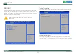
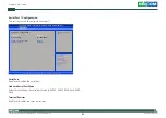
Hardware Monitor

This section is used to monitor hardware status such as temperature, fan 
speed and voltages.

CPU Temperature

Detects and displays the current CPU temperature. 

System Temperature

Detects and displays the current system temperature.

Vcore

Detects and displays the Vcore voltage.

Advanced

Version 2.17.1255. Copyright (C) 2016 American Megatrends, Inc.

Aptio Setup Utility - Copyright (C) 2016 American Megatrends, Inc.

→←: Select Screen
↑↓: Select Item
Enter: Select
+/-: Change Opt.
F1: General Help
F2: Previous Values
F3: Optimized Defaults
F4: Save & Exit
ESC: Exit

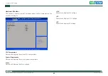
PC Health Status

CPU temperature

System temperature

Vcore

+12V

+3V

+5V

:  +35 

°

c

:  +41 

°

c

:  +0.83 V

:  +12.05 V

:  +3.33 V

:  +5.06 V

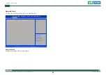
+12V

Detects and displays 12V voltage.

+3V

Detects and displays 3.3V voltage.

+5V

Detects and displays 5V voltage.

Summary of Contents for eLITE610

Page 1: ...NEXCOM International Co Ltd NEXCOM International Co Ltd Published March 2017 www nexcom com IoT Automation Solutions Business Unit HMI Panel PC eLITE610 User Manual...

Page 2: ...0 1 Specifications 2 Knowing Your eLITE610 3 Rear and Rear Bottom Side 3 Mechanical Dimensions 4 Chapter 2 Jumpers and Connectors Before You Begin 5 Precautions 5 Jumper Settings 6 Locations of the Ju...

Page 3: ...SATA Connector 22 SATA Power Connector 22 SIM Card Socket 23 Mini PCIe Slot PCIe mSATA 3G 24 Chapter 3 System Setup Removing the Rear Chassis Cover 25 Installing a TPM Module 25 Installing a SIM Card...

Page 4: ...XCOM International Co Ltd All other product names mentioned herein are registered trademarks of their respective owners Regulatory Compliance Statements This section provides the FCC compliance statem...

Page 5: ...Polybrominated diphenyl Ethers PBDE 0 1 or 1 000ppm In order to meet the RoHS compliant directives NEXCOM has established an engineering and manufacturing task force to implement the introduction of...

Page 6: ...aimed defect products that have been repaired or modified by persons who have not been authorized by NEXCOM or products which have been subjected to misuse abuse accident improper installation or usag...

Page 7: ...DIMM If the key parts are included please be noted clearly within the return form NEXCOM takes no responsibility for the parts which are not listed in the return form 4 Customers hold the responsibil...

Page 8: ...at returned a Basic Labor Cost and Testing Fee as Table listed b Parts Fee NEXCOM will charge for main IC chipsets such as the N B S B Super IO LAN Sound Memory and so on c 3rd party Device Fee produc...

Page 9: ...nd using the device note the following precautions Read all instructions carefully Do not place the unit on an unstable surface cart or stand Follow all warnings and cautions in this manual When repla...

Page 10: ...voltage and current rating marked on the product 10 All cautions and warnings on the equipment should be noted 11 If the equipment is not used for a long time disconnect it from the power source to a...

Page 11: ...rsion application software etc A complete description of the problem The exact wordings of the error messages Warning 1 Handling the unit carry the unit with both hands and handle it with care 2 Maint...

Page 12: ...20 Chung Cheng Rd ZhongHe District New Taipei City 23586 Taiwan R O C Tel 886 2 8226 7796 Fax 886 2 8226 7792 Email sales nexcom com tw www nexcom com tw NEXCOM Intelligent Systems Taichung Office 16F...

Page 13: ...nexcomitalia it NEXCOM Shanghai Room 603 604 Huiyinmingzun Plaza Bldg 1 No 609 Yunlin East Rd Shanghai 200333 China Tel 86 21 5278 5868 Fax 86 21 3251 6358 Email sales nexcom cn www nexcom cn NEXCOM...

Page 14: ...nformation The following provides ordering information for eLITE610 Barebone eLITE610 P N 10IE0061000X0 10 1 widescreen WSVGA with Intel Atom x5 E3930 Ethernet and USB 3 0 interfaces JMobile run time...

Page 15: ...uction Key Features 10 1 TFT color display LED backlight 1024 x 600 pixel WSVGA resolution 16 7M colors Resistive touchscreen 2x Giga LAN and 2x USB 3 0 1x RS232 422 485 communication port Extremely c...

Page 16: ...Yes Buzzer Yes Interface Ethernet 2x 10 100 1000Mbit USB 2x USB 3 0 Serial 1x RS232 422 485 BIOS configuration Ratings Power supply voltage 24 Vdc 19 2 to 28 8 Vdc Current consumption 1 64A at 24Vdc m...

Page 17: ...0 USB 3 0 ports used to connect USB 3 0 2 0 1 1 devices COM Port Supports RS232 422 485 compatible serial devices through BIOS setting DC Input Used to plug a DC power cord LAN 1 and LAN 2 Used to con...

Page 18: ...ction eLITE610 User Manual Mechanical Dimensions 282 OUTLINE 197 OUTLINE 224 32 V A 126 88 V A Active Area 222 72 125 28 Active Center 28 84 35 06 27 8 6 7 33 8 6 65 33 5 65 65 65 33 5 6 7 100 91 100...

Page 19: ...self before touching any internal components by touching a metal object Static electricity can damage many of the electronic components Humid environments tend to have less static electricity than dry...

Page 20: ...jumpers ensure that the jumper caps are placed on the correct pins When the jumper cap is placed on both pins the jumper is short If you remove the jumper cap or place the jumper cap on just one pin t...

Page 21: ...Rights Reserved 7 eLITE610 User Manual Chapter 2 Jumpers and Connectors Locations of the Jumpers and Connectors Top View JP4 JP3 J1 JP5 J5 CN5 JP8 J3 DEBUG1 USB4 JFW1 USB2 J4 LAN2 LAN1 USB1 COM1 SW1 P...

Page 22: ...Copyright 2017 NEXCOM International Co Ltd All Rights Reserved 8 eLITE610 User Manual Chapter 2 Jumpers and Connectors CN3 CN4 Bottom View...

Page 23: ...ector type 1x3 3 pin header 2 54mm pitch Connector location JP5 AT ATX Selection Connector type 1x3 3 pin header 2 0mm pitch Connector location JP6 Pin Settings 1 2 On Normal 2 3 On Clear BIOS 1 2 On...

Page 24: ...4 Panel Resolution Select Connector type 4 pin On Off Switch Connector location SW1 PWM Backlight Enable Select Connector type 2 pin On Off Switch Connector location SW2 SW1 1 SW1 2 SW1 3 SW1 4 Resol...

Page 25: ...3 Mechanical GND Connector Pin Definitions External I O Interface DC Power Input Connector type 1x3 3 pin terminal block Connector location PW1 Pin Definition Pin Definition 1 COM1_DCD 2 COM1_RXD 3 C...

Page 26: ...N2 ACT LINK ACT LINK 8 8 1 1 Pin Definition Pin Definition 1 LAN_MDI0P_1 2 LAN_MDI0N_1 3 LAN_MDI1P_1 4 LAN_MDI1N_1 5 LANTCT 6 GND 7 LAN_MDI2P_1 8 LAN_MDI2N_1 9 LAN_MDI3P_1 10 LAN_MDI3N_1 11 LAN_LED_LI...

Page 27: ...r type USB 3 0 port Type A Connector location USB1 USB 3 0 Port 2 Connector type USB 3 0 port Type A Connector location USB2 Pin Definition Pin Definition 1 5V 2 USB0 3 USB0 4 GND 5 USB3_RX 6 USB3_RX...

Page 28: ...ctors Internal Connectors DC Input Connector Connector type 1x4 4 pin header 2 0mm pitch Connector location JP3 DC Input Connector Connector type 1x4 4 pin header 2 0mm pitch Connector location JP4 Pi...

Page 29: ...0 User Manual Chapter 2 Jumpers and Connectors Power Button Connector type 1x2 2 pin header 2 0mm pitch Connector location JP2 Reset Button Connector type 1x2 2 pin header 2 0mm pitch Connector locati...

Page 30: ...Debug Only Connector type 2x3 6 pin header 2 0mm pitch Connector location JFW1 1 5 2 6 Pin Definition Pin Definition 1 1 8V 2 GND 3 SPI_CS 4 SPI_CK 5 SPI_SO 6 SPI_SI LCD Backlight Connector Connector...

Page 31: ...VCC_LCD 25 GND 26 GND 27 LVDS_CLK2 28 LVDS_DAT3 29 LVDS_CLK2 30 LVDS_DAT3 Pin Definition Pin Definition 1 VCOM 2 3V3_VDD 3 3V3_VDD 4 NC 5 RESET 6 STBYB 7 GND 8 AX0 _N 9 AX0 _P 10 GND 11 AX1 _N 12 AX1...

Page 32: ...Touch FPC Connector Connector type 1x4 4 pin header Connector location CN3 Pin Definition Pin Definition 1 Y_Up 2 X_Left 3 Y_Down 4 X_Right 1 4 Touch Sensor Connector Connector type 1x5 5 pin header...

Page 33: ...ers and Connectors USB Connector Dongle Connector type USB port Connector location USB3 1 4 Pin Definition Pin Definition 1 5V 2 USB3 3 USB3 4 GND Internal USB Connector Connector type 1x4 4 pin heade...

Page 34: ...onnector type 1x10 10 pin header 1 0mm pitch Connector location DEBUG1 Pin Definition Pin Definition 1 GND 2 Reset 3 LPC_CLK 4 LPC_FRAME 5 LPC_AD3 6 LPC_AD2 7 LPC_AD1 8 LPC_AD0 9 LPC_SERIRQ 10 3 3V 10...

Page 35: ...Connector Connector type 1x5 5 pin header JST 2 0mm pitch Connector location J1 5 1 Pin Definition Pin Definition 1 HDDLED 2 VCC5 3 GND 4 Standby Power 5V 5 Power LED 5V Remote Control Connector Conne...

Page 36: ...tors SATA Connector Connector type 1x7 7 pin header 1 27mm pitch Connector location CN5 7 1 Pin Definition Pin Definition 1 GND 2 SATA_TXP1_C 3 SATA_TXN1_C 4 GND 5 SATA_RXN1_C 6 SATA_RXP1_C 7 GND SATA...

Page 37: ...Co Ltd All Rights Reserved 23 eLITE610 User Manual Chapter 2 Jumpers and Connectors SIM Card Socket Connector location CN2 C5 C6 C7 C1 C2 C3 Pin Definition Pin Definition C1 UIM_PWR C2 UIM_RST C3 UIM...

Page 38: ...UIM_DATA 11 GPP_CLK1_N 12 UIM_CLK 13 GPP_CLK1_P 14 UIM_RESET 15 GND 16 UIM_VPP 17 NC 18 GND 19 NC 20 MINICARD1_DIS 21 GND 22 PCIE_RST 23 PCIE_RX2N mSATA_RxP 24 V3 3A_MINI 25 PCIE_RX2P mSATA_RxN 26 GND...

Page 39: ...sure the unit s power is off and disconnected from the power sources to prevent electric shock or system damage CAUTION CAUTION CAUTION 1 Locate and remove the mounting screws on the rear chassis cove...

Page 40: ...nal Co Ltd All Rights Reserved 26 eLITE610 User Manual Chapter 3 System Setup 2 Align the mounting holes on the TPM module to the standoffs and secure the module with screws 3 Connect the TPM cable to...

Page 41: ...Copyright 2017 NEXCOM International Co Ltd All Rights Reserved 27 eLITE610 User Manual Chapter 3 System Setup 4 Connect the other end of the TPM cable to the TPM connector on the motherboard...

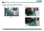
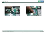
Page 42: ...International Co Ltd All Rights Reserved 28 eLITE610 User Manual Chapter 3 System Setup Installing a SIM Card and Mini PCIe Module 1 Locate the SIM card slot on the motherboard SIM Card Slot 2 Lift u...

Page 43: ...Copyright 2017 NEXCOM International Co Ltd All Rights Reserved 29 eLITE610 User Manual Chapter 3 System Setup 3 Place the SIM card into the slot 4 Close the cover and secure the SIM card into position...

Page 44: ...er Manual Chapter 3 System Setup 5 Insert the mini PCIe module into the mini PCIe slot at a 45 degrees angle until the gold plated connector on the edge of the module completely disappears inside the...

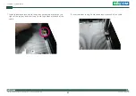
Page 45: ...d 31 eLITE610 User Manual Chapter 3 System Setup 7 Install the antenna jack end to the antenna mounting bracket on the right of the system and insert ring 1 onto the antenna jack end of the cable 8 In...

Page 46: ...hts Reserved 32 eLITE610 User Manual Chapter 3 System Setup 9 Attach the end of the RF cable onto the RF antenna connector on the mini PCIe module 10 Secure the rear chassis cover back to the system a...

Page 47: ...ystem Setup Installing an Internal USB Key 1 Loosen the screw on the USB fixing bracket 2 Plug the USB key into the USB connector and slide the fixing bracket towards the USB key Once the fixing brack...

Page 48: ...panel that corresponds to the rear dimensions of eLITE610 The thickness of the panel e g steel board plank acrylic board wall etc where you will mount eLITE610 must not exceed 6mm If the distance bet...

Page 49: ...configured with the values found in CMOS With easy to use pull down menus you can configure such items as Hard drives diskette drives and peripherals Video display type and display options Password p...

Page 50: ...be reported in one of two different ways If the error occurs before the display device is initialized a series of beeps will be transmitted If the error occurs after the display device is initialized...

Page 51: ...p screen it indicates that there are more available fields not shown on the screen Use the up and down arrow keys to scroll through all the available fields Submenu When appears on the left of a parti...

Page 52: ...59 10 0 1033 BXT Notebook Desktop Oxbow Hill CRB 06 FAB A 4096 MB 1866 MHz System Language Selects the language of the system System Date The date format is day month date year Day displays a day from...

Page 53: ...xit ESC Exit Trusted Computing Settings Trusted Computing ACPI Settings F81216SEC Super IO Configuration IT8528 H W Monitor CPU Configuration Network Stack Configuration USB Configuration Trusted Comp...

Page 54: ...ge Opt F1 General Help F2 Previous Values F3 Optimized Defaults F4 Save Exit ESC Exit Enables or Disables System ability to Hibernate OS S4 Sleep State This option may be not effective with some OS AC...

Page 55: ...422 RS485 or RS485 Auto Terminal Resistor Enables or disables the terminal resistor Advanced Version 2 18 1263 Copyright C 2016 American Megatrends Inc Aptio Setup Utility Copyright C 2016 American Me...

Page 56: ...stem temperature Vcore Detects and displays the Vcore voltage Advanced Version 2 17 1255 Copyright C 2016 American Megatrends Inc Aptio Setup Utility Copyright C 2016 American Megatrends Inc Select Sc...

Page 57: ...d Disabled Advanced Version 2 18 1263 Copyright C 2016 American Megatrends Inc Aptio Setup Utility Copyright C 2016 American Megatrends Inc Select Screen Select Item Enter Select Change Opt F1 General...

Page 58: ...ck Network Stack Enables or disables UEFI network stack Advanced Version 2 18 1263 Copyright C 2016 American Megatrends Inc Aptio Setup Utility Copyright C 2016 American Megatrends Inc Select Screen S...

Page 59: ...xit ESC Exit Enables Legacy USB support AUTO option disables legacy support if no USB devices are connected DISABLE option will keep USB devices available only for EFI applications USB Configuration U...

Page 60: ...trends Inc Select Screen Select Item Enter Select Change Opt F1 General Help F2 Previous Values F3 Optimized Defaults F4 Save Exit ESC Exit North Bridge South Bridge South Cluster Configuration North...

Page 61: ...m Enter Select Change Opt F1 General Help F2 Previous Values F3 Optimized Defaults F4 Save Exit ESC Exit Enable Disable SMBus Support SMBus Support Enabled Save Exit Advanced Chipset Boot Security Mai...

Page 62: ...Change Opt F1 General Help F2 Previous Values F3 Optimized Defaults F4 Save Exit ESC Exit Control the PCI Express Root Port AUTO To disable unused root port automatically for the most optimum power sa...

Page 63: ...pyright C 2016 American Megatrends Inc Version 2 18 1263 Copyright C 2016 American Megatrends Inc Aptio Setup Utility Copyright C 2016 American Megatrends Inc Aptio Setup Utility Copyright C 2016 Amer...

Page 64: ...able S0 State Security Save Exit Advanced Chipset Security Boot Main Version 2 18 1263 Copyright C 2016 American Megatrends Inc Aptio Setup Utility Copyright C 2016 American Megatrends Inc Select Scre...

Page 65: ...rican Megatrends Inc Select Screen Select Item Enter Select Change Opt F1 General Help F2 Previous Values F3 Optimized Defaults F4 Save Exit ESC Exit Number of seconds to wait for setup activation key...

Page 66: ...hanges and Reset To save the changes and reset select this field then press Enter A dialog box will appear Confirm by selecting Yes Discard Changes and Reset To exit the Setup utility and reboot the s...

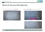
Page 67: ...l Rights Reserved 53 eLITE610 User Manual Appendix A Adjusting Screen Brightness Appendix A Adjusting Screen Brightness 1 In the Windows Control Panel menu select Power Options 2 Move the Screen brigh...

Reviews: