background image

Copyright © 2022 NEXCOM International Co., Ltd. All Rights Reserved.

54

FTA5180 Series User Manual 

Chapter 3: BIOS Setup

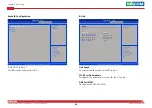
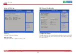
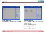
Security

Security

Version 2.22.1283. Copyright (C) 2022 AMI

Aptio Setup - AMI

→←: Select Screen

↑↓: Select Item

Enter: Select

+/-: Change Opt.

F1: General Help

F2: Previous Values

F3: Optimized Defaults

F4: Save & Exit

ESC: Exit

Set Administrator 

Password

Password Description

If ONLY the Administrator’s password is set,

then this only limits access to Setup and is

only asked for when entering Setup.

If ONLY the User's password is set, then this 

is a power on password and must be entered to 

boot or enter Setup. In Setup the User will

have Administrator rights.

The password length must be 

in the following range:

Minimum length 

3

Maximum length 

20

Administrator Password

Administrator Password

Select this to reconfigure the administrator’s password.

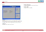
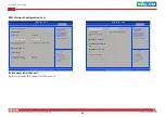
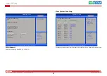
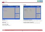
Boot

Setup Prompt Timeout

Selects the number of seconds to wait for the setup activation key.
65535(0xFFFF) denotes indefinite waiting.

Bootup NumLock State

This allows you to determine the default state of the numeric keypad. By 
default, the system boots up with NumLock on wherein the function of the 
numeric keypad is the number keys. When set to Off, the function of the 
numeric keypad is the arrow keys.

Version 2.22.1283. Copyright (C) 2022 AMI

Aptio Setup  - AMI

→←: Select Screen

↑↓: Select Item

Enter: Select

+/-: Change Opt.

F1: General Help

F2: Previous Values

F3: Optimized Defaults

F4: Save & Exit

ESC: Exit

Number of seconds to 

wait for setup 

activation key. 

65535 (0xFFFF) means 

indefinite waiting.

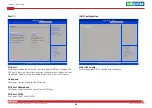
Boot Configuration

Setup Prompt Timeout

Bootup NumLock State

Quiet Boot

Boot mode select

AMI Virtual Devices

FIXED BOOT ORDER Priorities

Boot Option #1

Boot Option #2

Boot Option #3

Boot Option #4

Boot Option #5

Boot Option #6

Boot Option #7

Boot Option #8

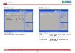
USB Key Drive BBS Priorities

[On]

[Disabled]

[UEFI]

[Disabled]

[Hard Disk]

[CD/DVD]

[USB Hard Disk]

[USB CD/DVD]

[USB Key: UEFI:

KingstonDataTraveler

3.0, Partition 1]

[USB Floppy]

[USB Lan]

[Network]

3

Boot

Summary of Contents for FTA 5180 Series

Page 1: ...NEXCOM International Co Ltd NEXCOM International Co Ltd Published May 2022 www nexcom com Network and Communication Solutions Fixed Wireless Access Telecom Appliance FTA 5180 Series User Manual ...

Page 2: ...Introduction Overview 1 Key Features 1 Hardware Specifications 2 Knowing Your FTA5180 3 Front Panel 3 Rear Panel 4 Chapter 2 Jumpers and Connectors Before You Begin 5 Precautions 5 Jumper Settings 6 Locations of the Jumpers and Connectors 7 Jumpers 8 RTC Clear 8 Connector Pin Definitions 9 External I O Interfaces 9 Power LED 9 PoE LED 9 Internal Connectors 10 PoE Header 10 PWM Controller SMBUS Hea...

Page 3: ...t System Power Button Header 16 CPLD JTAG 17 VGA 17 XDP Connector For Debug 18 Block Diagram 19 Chapter 3 BIOS Setup About BIOS Setup 20 When to Configure the BIOS 20 Default Configuration 21 Entering Setup 21 Legends 21 BIOS Setup Utility 23 Main 23 Advanced 24 Security 54 Boot 54 Save Exit 55 ...

Page 4: ...XCOM International Co Ltd All other product names mentioned herein are registered trademarks of their respective owners Regulatory Compliance Statements This section provides the FCC compliance statement for Class B devices and describes how to keep the system CE compliant Declaration of Conformity FCC This equipment has been tested and verified to comply with the limits for a Class B digital devi...

Page 5: ...Polybrominated diphenyl Ethers PBDE 0 1 or 1 000ppm In order to meet the RoHS compliant directives NEXCOM has established an engineering and manufacturing task force in to implement the introduction of green products The task force will ensure that we follow the standard NEXCOM development procedure and that all the new RoHS components and new manufacturing processes maintain the highest industry ...

Page 6: ...nsible for the safe packaging of defective products making sure it is durable enough to be resistant against further damage and deterioration during transportation In case of damages occurred during transportation the repair is treated as Out of Warranty Any products returned by NEXCOM to other locations besides the customers site will bear an extra charge and will be billed to the customer Repair...

Page 7: ...nd power supply are inconsistent with these instructions or the instructions for accessory modules contact the supplier to find out how you can ensure that your computer meets safety and regulatory requirements Cautions Electrostatic discharge ESD can damage system components Do the described procedures only at an ESD workstation If no such station is available you can provide some ESD protection ...

Page 8: ... the soft metal or plastic parts of the connectors Safety Information Before installing and using the device note the following precautions Read all instructions carefully Do not place the unit on an unstable surface cart or stand Follow all warnings and cautions in this manual When replacing parts ensure that your service technician uses parts specified by the manufacturer Avoid using the system ...

Page 9: ...uipment For safety reasons the equipment should be opened only by skilled person 14 If one of the following situations arises get the equipment checked by service personnel a The power cord or plug is damaged b Liquid has penetrated into the equipment c The equipment has been exposed to moisture d The equipment does not work well or you cannot get it to work according to the user s manual e The eq...

Page 10: ...on of the installed software operating system version application software etc A complete description of the problem The exact wordings of the error messages Warning 1 Handling the unit carry the unit with both hands and handle it with care 2 Maintenance to keep the unit clean use only approved cleaning products or clean with a dry cloth Conventions Used in this Manual Warning Information about ce...

Page 11: ...ity 23586 Taiwan R O C Tel 886 2 8226 7786 Fax 886 2 8226 7926 Email jennyshern nexcobot com www nexcobot com GreenBase Technology Corp 13F No 922 Zhongzheng Rd Zhonghe District New Taipei City 23586 Taiwan R O C Tel 886 2 8226 7786 Fax 886 2 8226 7900 Email vivianlin nexcom com tw www nexcom com tw DivioTec Inc 19F 1A No 97 Sec 4 ChongXin Rd Sanchong District New Taipei City 24161 Taiwan R O C Te...

Page 12: ...5 Yard 3 Gaolizhang Road Haidian District Beijing 100094 China Tel 86 10 5704 2680 Fax 86 10 5704 2681 Email marketing nexsec cn www nexsec cn NEXCOM Shanghai Room 406 407 Building C No 154 Lane 953 Jianchuan Road Minhang District Shanghai 201108 China Tel 86 21 5278 5868 Fax 86 21 3251 6358 Email sales nexcom cn www nexcom cn NEXCOM Surveillance Technology Corp Floor 8 Building B3 Xiufeng Industr...

Page 13: ...received is complete Your FTA5180 series package should have all the items listed in the table below Item Part Number Name Qty 1 5061711617X00 Ear Set for FTA1170 Ver A PANADVANCE 53 85x43x22mm SECC T 2 0mm Painting Pantone 8403C 1 2 5044440031X00 Rubber Foot Kang Yang RF20 5 4P 19 8x18x5 0mm 1 3 6023309081X00 Cable EDI 232091081804 RS COM Port DB9 Female to RJ45 8P8C L 1800mm 1 ...

Page 14: ...n Chapter 1 Product Introduction Key Features Intel Xeon D 1734NT processor 4 x RDIMM UDIMM socket support ECC non ECC up to 256GB 2 x M 2 2242 Key M with SATA signal 6 x 10G SFP ports 2 x 10GBaseT RJ45 PoE port Overview 2 x 2 5G RJ45 PoE ports 1 x LAN module slot Supports IPMI2 0 Supports Intel QAT TPM2 0 onboard ...

Page 15: ... PWR SSD SYS1 SYS2 PoE 8 x SMA connectors 2 x USB 3 0 ports 1 x RJ45 console port 1 x RJ45 management port 6 x 10G SFP ports 2 x 10GBaseT RJ45 PoE ports 2 x 2 5G RJ45 PoE ports 1 x VGA port 1 x LAN module slot 2 x AC power inlets 4 x Smart fans Interface Internal 1 x M 2 3042 Key B slot for 5G module 1 x mini PCIe slot for Wi Fi module Power 650W 1 1 redundant PSU Dimension and Weight Chassis dime...

Page 16: ...vices RJ45 Console Ports Used to connect to devices with RJ45 type console connection Management LAN Port Management LAN port used for managing the system USB 3 0 Port Used to connect USB 3 0 2 0 1 1 devices 10GBASE T RJ45 PoE Used to connect the system to a local area network 2 5G RJ45 PoE Used to connect the system to a local area network LAN Module Slot LAN module bay to install add on network ...

Page 17: ...nternational Co Ltd All Rights Reserved 4 FTA5180 User Manual Chapter 1 Product Introduction Rear Panel VGA Used to connect an analog VGA monitor SMA Connectors Used to plug coaxial cable and optical fibers VGA SMA Connectors ...

Page 18: ...ourself before touching any internal components by touching a metal object Static electricity can damage many of the electronic components Humid environments tend to have less static electricity than dry environments A grounding strap is warranted whenever danger of static electricity exists Precautions Computer components and electronic circuit boards can be damaged by discharges of static electr...

Page 19: ...the jumpers ensure that the jumper caps are placed on the correct pins When the jumper cap is placed on both pins the jumper is short If you remove the jumper cap or place the jumper cap on just one pin the jumper is open Refer to the illustrations below for examples of what the 2 pin and 3 pin jumpers look like when they are short on and open off Two Pin Jumpers Open Left and Short Right Three Pi...

Page 20: ...A5180 Series User Manual Chapter 2 Jumpers and Connectors Locations of the Jumpers and Connectors The figure below shows the location of the jumpers and connectors JP3 LED1 LED2 POE1 JP4 FAN1 FAN2 FAN3FAN4 FAN5 CN4 CN7 BAT1 JP6 JP7 JP9 IDV1 JTAG1 LCM1 CN9 CN11 JP1 VGA1 ...

Page 21: ...OM International Co Ltd All Rights Reserved 8 FTA5180 Series User Manual Chapter 2 Jumpers and Connectors Jumpers RTC Clear Connector type 1x3 3 pin header Connector location JP3 1 3 Pin Function 1 2 Normal 2 3 Clear CMOS ...

Page 22: ...tors Connector Pin Definitions External I O Interfaces Power LED Connector location LED1 Pin Definition Pin Definition 1 CPLD_PWR_LED 2 CPLD_HDD_LED 3 SW_SYS_LED 4 CPLD_GPIO1_LED PWR GPIO1 HDD SYS PoE LED Connector location LED2 Pin Definition Pin Definition 1 POE_LED1 2 POE_LED2 3 POE_LED3 4 POE_LED4 POE1 POE4 POE2 POE3 ...

Page 23: ...9 SMB_CLK_POE_R 10 POE_RST_N 11 GND 12 NC 13 POE MAIN POK 14 VPORT_NEG_10G_OUT4 15 P54V 16 VPORT_NEG_10G_OUT3 17 P54V 18 VPORT_NEG_10G_OUT2 19 P54V 20 VPORT_NEG_10G_OUT1 21 VPORT_NEG_10G_OUT8 22 VPORT_NEG_10G_OUT5 23 VPORT_NEG_10G_OUT7 24 VPORT_NEG_10G_OUT6 PoE Header Connector type 2x12 24 pin header Connector location POE1 1 23 2 24 PWM Controller SMBUS Header Connector type 1x3 3 pin header Con...

Page 24: ...nd Connectors LCM Reserved Connector type 1x4 4 pin header Connector location LCM1 Pin Definition Pin Definition 1 PWR_LCM 2 SP_LCM_TXD 3 SP_LCM_RXD 4 GND Fan Wafer Connector Connector type 1x4 4 pin header Connector location FAN1 FAN2 FAN3 FAN4 FAN5 Pin Definition Pin Definition 1 GND 2 P12V 3 TACH 4 PWM 1 4 4 1 ...

Page 25: ... P12V_AUX 4 P12V_AUX 5 P12V_AUX 6 P12V_AUX 7 P12V_AUX 8 P5V_STBY 9 GND 10 GND 11 GND 12 GND 13 GND 14 GND 15 GND 16 GND Internal Power Connector Connector type 2x8 16 pin header Connector location CON4 Pin Definition Pin Definition 1 GND 2 GND 3 GND 4 GND 5 P12V 6 P12V 7 P12V 8 P12V Internal Power Connector Connector type 2x4 8 pin header Connector location CN9 1 15 2 16 1 7 2 8 ...

Page 26: ...or type 2x3 6 pin header Connector location CN11 Pin Definition Pin Definition 1 NC 2 SMB ALERT_A_CAB 3 NC 4 SMB ALERT_B_CAB 5 SMB_PMBUS1_STBY_LVC3_R_SCL 6 PRESENT_IN_A_CAB 7 SMB_PMBUS1_STBY_LVC3_R_SDA 8 PRESENT_IN_B_CAB 9 NC 10 GND 11 PS_ON_R 12 P3V3_AUX 13 NC 14 P3V3_AUX 15 PW_OK_A_CAB 16 GND 17 PW_OK_B_CAB 18 NC 19 NC 20 NC Power signal to power supply Connector type 2x10 20 pin header Connecto...

Page 27: ...ser Manual Chapter 2 Jumpers and Connectors SYS RTC Holder Connector type 1x3 3 pin header Connector location BAT1 1 3 Pin Function 1 RTC_BAT 2 RTC_BAT 3 GND UART from CPLD Reserved Connector type 1x3 3 pin header Connector location JP6 1 3 Pin Function 1 PLD_PR20C 2 GND 3 PLD_PR20D ...

Page 28: ...pers and Connectors JTAG header from CPLD or BMC select Connector type 1x2 2 pin header Connector location JP9 Pin Function 1 JTAG_SEL 2 GND BMC UART Debug Connector type 1x4 4 pin header Connector location JP7 Pin Definition Pin Definition 1 P3V3_BMC 2 BMC_CPLD_DEBUG_RXD 3 BMC_CPLD_DEBUG_TXD 4 GND 1 2 1 4 ...

Page 29: ..._PVCCIN_CPU 15 FM_CPU_MSMI_LVT3_R_N 16 GND 17 P1V2_VDDQ 18 PWRGD_PCH_PWROK 19 NC 20 PVCCIN_CPU 21 PWRGD_PVNN_NAC 22 P2V5_PVPP 23 NC 24 FM_CPU_ERR2_LVT3_N 25 FM_CPU_CATERR_LVT3_R_N 26 GND 27 FM_CPU_PROCHOT_LATCH_ LVT3_R_N 28 FM_CPU_ERR1_LVT3_N 29 FM_CPU_THERMTRIP_LATCH_ LVT3_R_N 30 FM_CPU_ERR0_LVT3_N 31 PWRGD_DRAMPWRGD_R2 32 PVTT 33 PWRGD_PS_PWROK_IDV 34 FM_SLPS3_N 35 FM_SLPS4_N 36 GND 37 SMB_SMLIN...

Page 30: ...inition 1 P3V3_CPLD 2 GND 3 JTAG_TCK_CPLD 4 JTAG_TDO_CPLD 5 JTAG_TDI_CPLD 6 JTAG_TMS_CPLD Pin Definition Pin Definition 1 VGA_VCC 2 GND 3 NC 4 SMB_BMC_DDC_SCL_R1 5 SMB_BMC_DDC_SDA_R1 6 NC 7 V_BMC_GFX_REAR_VSYN_R3 8 GND 9 V_BMC_GFX_REAR_HSYN_R3 10 NC 11 GND 12 V_BMC_GFX_REAR_BLU_R1 13 GND 14 V_BMC_GFX_REAR_GRN_R1 15 GND 16 V_BMC_GFX_REAR_RED_R1 VGA Connector type 1x16 16 pin header Connector locati...

Page 31: ...BG_PTI_D1 21 TRC_DFX_D1 22 TP_PCH_DBG_PTI_D2 23 TRC_DFX_D2 24 TP_PCH_DBG_PTI_D3 25 TRC_DFX_D3 26 TP_PCH_DBG_PTI_D4 27 TRC_DFX_D4 28 TP_PCH_DBG_PTI_D5 29 TRC_DFX_D5 30 TP_PCH_DBG_PTI_D6 31 TRC_DFX_D6 32 TP_PCH_DBG_PTI_D7 33 TRC_DFX_D7 34 TP_RSVD1_LTB_CONN 35 TRC_DFX_D8 36 FM_GBE_SDP_TIMESYNC2_R 37 TRC_DFX_D9 38 DBP_CPU_FBRK_N 39 TRC_DFX_D10 40 XDP_PWR_BTN_N Pin Definition Pin Definition 41 TRC_DFX_...

Page 32: ...ent port RUNBMC AST2500 VGA Super IO UART Reserved for LCM RJ45 Console 2xUSB3 0 6x SFP X710 TM4 i225 i225 Microsemi PD69208T4 PoE SlimSAS OCP 4C PCIex8 Reserve for Switch Mini PCIe slot M 2 B key 3052 3042 Wireless 10G LAN 4x RJ45 with PoE 90Wx4 BMC 2xSATA only PCIe2x1 PCIex1 NC SI SoC MAC controller 0 10Gx4 10Gx2 PCIe3x8 PCIe3x1 10Gx2 2 5Gx2 PCIe3x1 PCIe4x8 PCIe4x8 PCIe3x1 PCIe3x1 USB3 0x1 USB2 ...

Page 33: ...system is configured with the values found in CMOS With easy to use pull down menus you can configure items such as Hard drives diskette drives and peripherals Video display type and display options Password protection from unauthorized use Power management features The settings made in the setup program affect how the computer performs It is important therefore first to try to understand all the ...

Page 34: ...ntered the error will be reported in one of two different ways If the error occurs before the display device is initialized a series of beeps will be transmitted If the error occurs after the display device is initialized the screen will display the error message Powering on the computer and immediately pressing allows you to enter Setup Legends Key Function Moves the highlight left or right to se...

Page 35: ...setup screen it indicates that there are more available fields not shown on the screen Use the up and down arrow keys to scroll through all the available fields Submenu When appears on the left of a particular field it indicates that a submenu which contains additional options are available for that field To display the submenu move the highlight to that field and press ...

Page 36: ...xit ESC Exit Choose the system default language BIOS Information BIOS Vendor Core Version Compliancy Project Version Build Date and Time CPLD FW Version Current BIOS Access Level Memory Information Total Memory System Language System Date System Time American Megatrends 5 25 UEFI 2 8 PI 1 7 G158 0 03 x64 04 13 2022 13 17 01 07 BIOS1 Administrator 4096 MB English Wed 04 31 2022 14 36 31 Access Leve...

Page 37: ...rding to your preference Version 2 22 1283 Copyright C 2022 AMI Aptio Setup AMI Select Screen Select Item Enter Select Change Opt F1 General Help F2 Previous Values F3 Optimized Defaults F4 Save Exit ESC Exit Trusted Computing Settings Trusted Computing NCT6686D Super IO Configuration Hardware Monitor Serial Port Console Redirection PCI Subsystem Settings USB Configuration Network Stack Configurat...

Page 38: ...pec Version TPM 2 0 7 62 IFX Enable SHA 1 SHA256 SHA 1 SHA256 Enabled Enabled None Enabled Enabled Enabled TCG_2 1 3 TIS Security Device Support Enables or disables BIOS support for security device O S will not show Security Device TCG EFI protocol and INT1A interface will not be available SHA 1 PCR Bank Enables or disables SHA 1 PCR Bank SHA256 PCR Bank Enables or disables SHA256 PCR Bank Pending...

Page 39: ...s Values F3 Optimized Defaults F4 Save Exit ESC Exit Set Parameters of Serial Port 1 COMA NCT6686D Super IO Configuration Super IO Chip Serial Port 1 Configuration NCT6686D Serial Port 1 Configuration This section is used to configure serial port 1 Serial Port Enables or disables the serial port Change Settings Selects an optimal setting for the Super IO device Advanced Version 2 22 1283 Copyright...

Page 40: ...onsole Redirection Settings Redirection COM Port Resolution Redirect After POST COM0 80x24 Always Enable Hardware Monitor This section is used to monitor hardware status such as temperature fan speed and voltages CPU and System Temperature Detects and displays the current CPU and system temperature Fan1 to Fan5 Speed Detects and displays the current fan1 to fan5 speed P12V to PVNN_PCH Detects and ...

Page 41: ...Redirection Enabled EMS Console Redirection Settings Enabled COM0 Console Redirection Settings Advanced Version 2 22 1283 Copyright C 2022 AMI Aptio Setup AMI Select Screen Select Item Enter Select Change Opt F1 General Help F2 Previous Values F3 Optimized Defaults F4 Save Exit ESC Exit Emulation ANSI Extended ASCII char set VT100 ASCII char set VT100Plus Extends VT100 to support color function ke...

Page 42: ...pport Enables or disables VT UTF8 combo key support Recorder Mode When this field is enabled only text will be sent This is to capture the terminal data Resolution 100x31 Enables or disables extended terminal resolution Putty Keypad Selects the Putty keyboard emulation type PCI Subsystem Settings This section is used to configure the PCI Above 4G Decoding Enables or disables decoding of 64 bit dev...

Page 43: ...equest Auto Auto Maximum Payload Selects the maximum TLP payload size of the PCI Express devices Maximum Read Request Selects the maximum read request size of the PCI Express devices PCI Express GEN 2 Settings Advanced Version 2 22 1283 Copyright C 2022 AMI Aptio Setup AMI Select Screen Select Item Enter Select Change Opt F1 General Help F2 Previous Values F3 Optimized Defaults F4 Save Exit ESC Ex...

Page 44: ...rt Enable Enables Legacy USB Auto Disables support for Legacy when no USB devices are connected Disable Keeps USB devices available only for EFI applications XHCI Hand off This is a workaround for OSes that does not support XHCI hand off The XHCI ownership change should be claimed by the XHCI driver USB Configuration This section is used to configure the USB USB Mass Storage Driver Support Enables...

Page 45: ...Advanced Version 2 22 1283 Copyright C 2022 AMI Aptio Setup AMI Select Screen Select Item Enter Select Change Opt F1 General Help F2 Previous Values F3 Optimized Defaults F4 Save Exit ESC Exit Enable Disable CSM Support Compatibility Support Module Configuration CSM Support CSM16 Module Version GateA20 Active INT19 Trap Response Option ROM execution Network Storage Video Other PCI devices Enabled ...

Page 46: ...vices Enables or disables the boot option for legacy PCI devices Version 2 22 1283 Copyright C 2022 AMI Aptio Setup AMI Select Screen Select Item Enter Select Change Opt F1 General Help F2 Previous Values F3 Optimized Defaults F4 Save Exit ESC Exit PCH Parameters PCH IO Configuration Server ME Configuration IRC Firmware Information Setup Warning Setting items on this Screen to incorrect values may...

Page 47: ...ion PCH IO Configuration SATA Configuration Device options settings USB Configuration Enters the USB Configuration submenu State After G3 Configures the power state when power is re applied after a power failure G3 state S0 State Version 2 22 1283 Copyright C 2022 AMI Aptio Setup AMI Select Screen Select Item Enter Select Change Opt F1 General Help F2 Previous Values F3 Optimized Defaults F4 Save ...

Page 48: ...les Serial ATA port 1 Port 3 Enables or disables Serial ATA port 3 Hot Plug Enables or disables hot plugging feature on Serial ATA port 1 or 3 Enabled Not Installed Enabled Disabled Not Installed Enabled Disabled Version 2 22 1283 Copyright C 2022 AMI Aptio Setup AMI Select Screen Select Item Enter Select Change Opt F1 General Help F2 Previous Values F3 Optimized Defaults F4 Save Exit ESC Exit Sel...

Page 49: ...s 1 ME Firmware Status 2 Current State Error Code Recovery Cause Platform Configuration General ME Configuration 11 5 0 3 67 N A 11 5 0 3 67 0x00000255 0x88110006 Operational No Error N A Version 2 22 1283 Copyright C 2022 AMI Aptio Setup AMI Select Screen Select Item Enter Select Change Opt F1 General Help F2 Previous Values F3 Optimized Defaults F4 Save Exit ESC Exit Active Firmware Tag Active F...

Page 50: ... Common RefCode Configuration submenu Memory Configuration Enters the Memory Configuration submenu IIO Configuration and Advanced Power Management Configuration Enters the IIO Configuration and Advanced Power Management Configuration submenu Version 2 22 1283 Copyright C 2022 AMI Aptio Setup AMI Select Screen Select Item Enter Select Change Opt F1 General Help F2 Previous Values F3 Optimized Defau...

Page 51: ...Per Package Processor 0 Version Hyper Threading ALL Check CPU BIST Result Hardware Prefetcher Adjacent Cache Prefetch Extended APIC AES NI Socket Configuration Hyper Threading ALL Enables or disables hyper threading technology Check CPU BIST Result Enables or disables Check CPU BIST Result Hardware Prefetcher Enables or disables the MLC streamer prefetcher Adjacent Cache Prefetcher Enables or disa...

Page 52: ... Version 2 22 1283 Copyright C 2022 AMI Aptio Setup AMI Select Screen Select Item Enter Select Change Opt F1 General Help F2 Previous Values F3 Optimized Defaults F4 Save Exit ESC Exit 0 Enable all cores FFFFFFFFFFF Disable all cores NOTE At least one core per CPU must be enabled Disabling all cores is an invalid configuration CPU Socket 0 Configuration Available Bitmap Core Disable Bitmap Hex Soc...

Page 53: ...FG Size Select MMCFG size Virtual Numa Enables or disables Non Uniform Memory Access support Auto 2T 64G Disable Memory Configuration Version 2 22 1283 Copyright C 2022 AMI Aptio Setup AMI Select Screen Select Item Enter Select Change Opt F1 General Help F2 Previous Values F3 Optimized Defaults F4 Save Exit ESC Exit Maximum Memory Frequency Selections in Mhz If Enforce POR is disabled user will be...

Page 54: ...2 AMI Aptio Setup AMI Select Screen Select Item Enter Select Change Opt F1 General Help F2 Previous Values F3 Optimized Defaults F4 Save Exit ESC Exit Maximum Memory Frequency Selections in Mhz If Enforce POR is disabled user will be able to run at higher frequencies than the memory support limited by processor support IIO Configuration Socket0 Configuration IOAT Configuration Intel VT for Directe...

Page 55: ...elects PCIe port Bifurcation for selected slot s R Link Version 2 22 1283 Copyright C 2022 AMI Aptio Setup AMI Select Screen Select Item Enter Select Change Opt F1 General Help F2 Previous Values F3 Optimized Defaults F4 Save Exit ESC Exit Choose Link Speed for this PCIe port R Link Link Speed PCI E Port DeEmphasis PCI E Port Link Status PCI E Port Link Max PCI E Port Link Speed DMI Port MPSS Sock...

Page 56: ...t Configuration PCI E Port Enables or disables the PCIe port In auto mode the BIOS will remove the EXP port if there is no device or errors on that device and the device is not HP capable Disable is used to disable the port and hide its CFG space Link Speed Configures the link speed for the PCIe port In auto mode the BIOS will remove the EXP port if there is no device or errors on that device and ...

Page 57: ...ce and the device is not HP capable Disable is used to disable the port and hide its CFG space Link Speed Configures the link speed for the PCIe port PCI E Port DeEmphasis Configures the de emphasis control for the PCIe port PCI E Port MPSS Configures the PCI e Port MPSS In auto mode the BIOS will remove the EXP port if there is no device or errors on that device and the device is not HP capable E...

Page 58: ...AT Function 1 Items DMA Yes No Snoop No IOAT Function 2 Items DMA Yes No Snoop No IOAT Function 3 Items Socket Configuration DMA Enables or disables DMA No Snoop Enables or disables No Snoop function for each CB device Version 2 22 1283 Copyright C 2022 AMI Aptio Setup AMI Select Screen Select Item Enter Select Change Opt F1 General Help F2 Previous Values F3 Optimized Defaults F4 Save Exit ESC Ex...

Page 59: ...MAR ACPI tables Interrupt Remapping Configures Interrupt Remapping X2APIC Opt Out Enables or disables X2APIC mode Enable Disable Intel Virtualization Techonology for Directed I O VT d by reporting the I O device assignment to VMM through DMAR ACPI Tables Enable Auto Disable Advanced Power Management Configuration Version 2 22 1283 Copyright C 2022 AMI Aptio Setup AMI Select Screen Select Item Ente...

Page 60: ...Enable Disable EIST P States Base Config 3 10 10 10 20 15 15 067 056 056 102 102 102 CPU P State Control Version 2 22 1283 Copyright C 2022 AMI Aptio Setup AMI Select Screen Select Item Enter Select Change Opt F1 General Help F2 Previous Values F3 Optimized Defaults F4 Save Exit ESC Exit Hardware PM State Control Hardware P State Disable Socket Configuration Hardware P States Disable Hardware choo...

Page 61: ...rm Reset To perform a BMC warm reset select this field then press Enter FAILED 32 81 1 03 2 0 KCS Enabled Power Restore Unspecified Version 2 22 1283 Copyright C 2022 AMI Aptio Setup AMI Select Screen Select Item Enter Select Change Opt F1 General Help F2 Previous Values F3 Optimized Defaults F4 Save Exit ESC Exit Changed this to enable or disable event logging for error progress codes during boot...

Page 62: ...ight C 2022 AMI Aptio Setup AMI Select Screen Select Item Enter Select Change Opt F1 General Help F2 Previous Values F3 Optimized Defaults F4 Save Exit ESC Exit Select to configure LAN channel parameters statiscally or dynamically by BIOS or BMC Unspecified option will not modify any BMC network parameters during BIOS BMC network configuration Configure IPv4 support Lan channel 1 Configuration Add...

Page 63: ... Length 0 IPv6 address status IPv6 DHCP Algorithm Server Mgmt BMC Network Configuration Cont IPv6 Support LAN Channel 1 Enables or disables IPv6 support for LAN channel 1 Enabled Unspecified DynamicAddressBmcDhcp Active DHCPv6 Version 2 22 1283 Copyright C 2022 AMI Aptio Setup AMI Select Screen Select Item Enter Select Change Opt F1 General Help F2 Previous Values F3 Optimized Defaults F4 Save Exi...

Page 64: ... 22 1283 Copyright C 2022 AMI Aptio Setup AMI Select Screen Select Item Enter Select Change Opt F1 General Help F2 Previous Values F3 Optimized Defaults F4 Save Exit ESC Exit HEX 01 00 02 70 A2 FF 4E 01 00 04 12 00 6F 05 00 FF Generator ID BIOS Channel 0 Sensor Number 0x00 Unspecified No of log entries in SEL 3639 DATE TIME SENSOR TYPE 01 01 12 00 01 52 01 01 12 00 01 52 10 07 21 01 30 26 10 06 21...

Page 65: ...on to add a user Delete User Option to delete a user Change User Settings Option to change user settings Version 2 22 1283 Copyright C 2022 AMI Aptio Setup AMI Select Screen Select Item Enter Select Change Opt F1 General Help F2 Previous Values F3 Optimized Defaults F4 Save Exit ESC Exit Enter BMC User Name BMC Add User Details User Name User Password User Access Channel No User Privelege Limit Se...

Page 66: ...Version 2 22 1283 Copyright C 2022 AMI Aptio Setup AMI Select Screen Select Item Enter Select Change Opt F1 General Help F2 Previous Values F3 Optimized Defaults F4 Save Exit ESC Exit Enter BMC User Name BMC Change User Settings User Name User Password Change User Password User Access Channel No User Privelege Limit Server Mgmt Change User Settings User Name and User Password Enter the login usern...

Page 67: ... the number of seconds to wait for the setup activation key 65535 0xFFFF denotes indefinite waiting Bootup NumLock State This allows you to determine the default state of the numeric keypad By default the system boots up with NumLock on wherein the function of the numeric keypad is the number keys When set to Off the function of the numeric keypad is the arrow keys Version 2 22 1283 Copyright C 20...

Page 68: ... select this field then press Enter A dialog box will appear Confirm by selecting Yes Discard Changes and Reset To exit the Setup utility and reset without saving the changes select this field then press Enter You may be prompted to confirm again before exiting Restore Defaults To restore the BIOS to default settings select this field then press Enter A dialog box will appear Confirm by selecting ...

Page 69: ...anual Chapter 3 BIOS Setup Boot Override To bypass the boot sequence from the Boot Option List and boot from a particular device select the desired device and press Enter Launch EFI Shell from filesystem device To launch EFI shell from a filesystem device select this field and press Enter ...

Reviews: