Copyright © 2021 NEXCOM International Co., Ltd. All Rights Reserved.
7
NDiS B360 User Manual
Chapter 2: Jumpers and Connectors
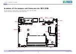
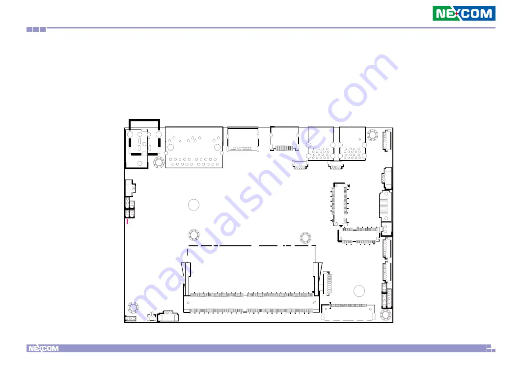
Locations of the Jumpers and Connectors for NDiS B360
The figure below is the top view of the mainboard used in the NDiS B360.
It shows the locations of the jumpers and connectors.
H2
B9
B2
B1 A9
A2
A1
B10
A10
M12
H5
GND
GND
GND
GND
H7
H6
L5
M14
H4
LCD_PWR
M2E_1
2
1
1
1
3
1
1
2
2
2
1
1
1
1
1
6
1
1
1
7
75
75
74
74
6
2
1
1
9
9
4
4
1
1
1
1
1
40
1
10
2
144
146
260
4
3
1
1
1
259
1
1
5
2
2
2
19
19
14
14
18
18
4
5
4
5
1
4
9
1
9
1
9
20
2
3
5
4
HDMI
DP1
LAN1
FAN
J2
DCIN2
J1
JP3
JP2
JP1
CLRCMOS
AT_ATX
MIC_LOUT1
SPK1
SATA
PWR1
COM1
COM2
JP5
JP4
M2E
USB3_1 USB3_2
USB2_78P
USB2_910P
GPIO1
EDP
M2M
LAN2

