background image

4 System configuration 

4.1 


Login 

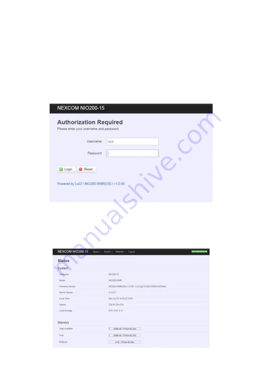
To access the NIO200WMR device, you may open a browser to access the Web GUI via 

default IP address 192.168.1.1.    The login Web page requires login information as below: 


Default login information is:   

Login: root 

Password: admin 

After successful login, 

you will see the “Status” page of the device Web UI. 


Summary of Contents for NIO200

Page 1: ...NIO200WMR User Manual V1 2 ...

Page 2: ...r installation 16 3 2 2 Power installation 19 3 2 3 Antenna installation 19 3 2 4 Earth grounding 20 3 2 5 Mounting of NIO200 Series 20 4 System configuration 23 4 1 Login 23 4 2 Status 25 4 2 1 Overview 25 4 2 2 Firewall 29 4 2 3 Routes 29 4 2 4 System Log 31 4 2 5 Kernel Log 31 4 2 6 Processes 32 4 2 7 Real time Graphic 32 4 3 System 36 4 3 1 System 36 4 3 2 Administration 39 4 3 3 Backup Flash ...

Page 3: ...1 Mesh Advanced 55 4 4 4 DHCP and DNS 58 4 4 4 1 General Settings 59 4 4 4 2 Resolve and Hosts Files 60 4 4 4 3 TFTP Settings 60 4 4 4 4 Advanced Settings 61 4 4 5 Hostnames 62 4 4 6 Static Routes 63 4 4 7 Diagnostics 65 4 4 8 Firewall 66 4 4 8 1 General Settings 66 4 4 8 2 Port Forwards 67 4 4 8 3 Traffic Rules 67 4 4 8 4 Custom Rules 68 ...

Page 4: ... product in use by constantly checking its manual posted on our website http www nexcom com NEXCOM shall not be liable for direct indirect special incidental or consequential damages arising out of the use of any product nor for any infringements upon the rights of third parties which may result from such use Any implied warranties of merchantability or fitness for any particular purpose is also d...

Page 5: ...ay detergents for cleaning 4 For plug in equipment the power outlet socket must be located near the equipment and must be easily accessible 5 Keep this equipment away from humidity 6 Put this equipment on a stable surface during installation Dropping it or letting it fall may cause damage 7 The openings on the enclosure are for air convection to protect the equipment from overheating DO NOT COVER ...

Page 6: ...ot included by attaching it to the grounding screw on the unit and to a good ground connection Earth Green Yellow wire 18AWG the minimum cross sectional area of Earth conductor shall equal to Input wiring cable 17 The front of the Equipment requires wiring terminals with the following specifications Wire size 30 12 AWG 0 0509 3 3088 mm Wire Type copper wire only Terminal Blocks Torque 5 lb In 0 56...

Page 7: ... ou des zones non dangereuses uniquement WARNING EXPLOSION HAZARD DO NOT CONNECT OR DISCONNECT WHEN ENERGIZED AVERTISSEMENT RISQUE D EXPLOSION NE PAS CONNECTER NI DÉCONNECTER LORSQU IL EST EN CHARGE Product is UL Listed with UL Listed Fittings for use with liquid tight flexible metal conduit This wiring method is suitable for flexible connections in accordance with Article 501 10 B 2 of the Nation...

Page 8: ...lied with the chassis power supply and accessory modules If the instructions for the chassis and power supply are inconsistent with these instructions or the instructions for accessory modules contact the supplier to find out how you can ensure that your computer meets safety and regulatory requirements 1 Handling the unit carry the unit with both hands and handle it with care 2 Opening the enclos...

Page 9: ...ain situations which if not observed can cause personal injury This will prevent injury to yourself when performing a task Caution Information to avoid damaging components or losing data Note Provides additional information to complete a task easily Note The surface temperature of enclosure may exceed 70 under working condition Remarque La température de surface de l enceinte peut dépasser 70 dans...

Page 10: ...outing capability which serves as an interface between the radio network and the backbone network BBR Backbone Router Blacklisted channel A channel on which transmission is prohibited Broadcast Transmission intended for all the devices in an ISA100 11a network used for advertisements with all devices including the BBR or for receive links for field devices only CCA backoffs The count of transmissi...

Page 11: ...esentation of the network topology GW Gateway Input output A device with minimum characteristics required to participate in an ISA100 11a network and which provides or uses data from other devices ISA100 11a A communication protocol used in wireless networks set up by the Wireless Compliance Institute JSON JavaScript Object Notation LAN Local Area Network Link A momentary or persistent interconnec...

Page 12: ... the ISA100 11a network that supervises the various operational aspects of a network other than security TR Transceiver the BBR radio User Application Process From ISA100 11a standard An active process within the highest portion of the application layer that is the user of OSI Open Systems Interconnection services UTC Coordinated Universal Time A universal timekeeping standard that is based on the...

Page 13: ...blishes robust access and backbone infrastructure To meet the requirement of critical environment NIO200WMR equips with wide temperature 40 75 C IP67 protection highest standard level 4 EMC immunity CID2 and ATEX anti explosive capability For security consideration NIO200WMR gives user versatile selection of different encryption pre shared key and Enterprise black list and white list protection me...

Page 14: ...ree liquid tight cable gland or conduit based on the ATEX or CID2 model used only for DC power input and Ethernet port Two pin DC power connector for 12 48 VDC power input Grounding screws Four outdoor antennas for evaluation purpose when deployed in field site the antenna may be changed to meet the application requirement ...

Page 15: ...ble from the PC where the browser is running 3 2Hardware installation Guide Hardware connection of NIO200 includes the power Ethernet interfaces and RF connectors The installation of NIO200 should be carefully done with standard waterproof connectors accessories in the package CID2 conduit connector ATEX cable gland connector Note the mounting of NIO200 should always let water proof connectors dow...

Page 16: ...ollow the steps below Put conduit through cap nut and gland packing Position the ferrule at the end of the conduit Just have the bottom of ferrule cover the conduit over tighten may enlarge conduit diameter and loosen Pass DC power cable or Ethernet cable through conduit Connect connector into Insert the conduit with Push gland packing and ...

Page 17: ...user should implement with Flexible Metal Conduit Liquid tight which meets UL360 standard Here is the requirement of the diameter and size information for the selection of Metal Conduit that mate with NIO200 conduit connectors B Installation of cable gland connector for ATEX model To install cable gland with power Ethernet cable on NIO200 enclosure please follow the steps below ...

Page 18: ...ration at the left 2 Connect cable gland to NIO200 unit Screw up the tips of power cable to green power connector Fit the power cable to the left screw hole and tightly fasten cable gland to enclosure of NIO200 unit Fit the Ethernet cable into the LAN or WAN hole on the enclosure Tightly fasten cable gland to enclosure of NIO200 unit ...

Page 19: ...larity of power cord fits the polarity drawing in this diagram When use PoE power source just plug the Ethernet cable into PoE port If the power connects correctly then the Power LED will light accordingly 3 2 3 Antenna installation IWSN antenna connector for connecting to ISA100 or WirelessHART not used in NIO200WMR Wi Fi antenna connector for Wi Fi Mesh connection WLAN 1 WLAN 2 ...

Page 20: ... enclosure 1 Be sure to ground the 0 75mm2 ground screw with an appropriate grounding wire Earth Green Yellow wire 18AWG not included by attaching it to a good earth ground connection 2 There must be a disconnect device in front of NIO200 series to keep the worker or field side maintainer be cautious and aware to close the general power supply before they start to do maintenance 3 The disconnect d...

Page 21: ...2 Be sure to fasten the mounting kit with horizontal position as below 3 Hang on NIO200 to the wall with water proof connector at the bottom direction B Pole mounting method ...

Page 22: ......

Page 23: ...e you may open a browser to access the Web GUI via default IP address 192 168 1 1 The login Web page requires login information as below Default login information is Login root Password admin After successful login you will see the Status page of the device Web UI ...

Page 24: ...e changes at the bottom of WebUI Unsaved Changes UNSAVED CHANGES provides the help to see the parameters which were not saved applied Click Save Apply button to save the parameters Auto Refresh Toggle AUTO REFRESH button to turn on off WebUI refresh function automatically ...

Page 25: ...n 4 2 1 Overview To see NIO200 over all status click Overview to displays the current system information and interface connection status 4 2 1 1 System Hostname Displays NIO200 host name Model Displays NIO200 HW basic information Firmware Version Displays NIO200 firmware version Kernel Version Displays NIO200 Kernel version Local Time Displays NIO200 current date and time Uptime Displays how long ...

Page 26: ...tes 4 2 1 2 Memory Total Available Displays the available memory in percentage Free Displays free memory of NIO200 Buffered Displays buffer memory used in the system 4 2 1 3 Network IPv4 WAN Status Displays current connecting IPv4 information IPv6 WAN Status Displays current connecting IPv6 information Active Connections Displays current active connections ...

Page 27: ...luding IPv4 MAC address and leasing time 4 2 1 5 DHCPv6 Leases This displays information about hosts Personal Computers or electronic devices that are connected to NIO200 including IPv6 DUID and leasing time 4 2 1 6 Wireless This displays Wireless information about NIO200 for radio 0 1 SSID Displays the name of the wireless network ...

Page 28: ...eless data rate BSSID Displays MAC address of this radio Encryption Displays current encryption setting 4 2 1 7 Associated Stations Displays current associated device information Personal Computers or electronic devices with NIO200WMR including device s MAC address signal level noise connecting data rate ...

Page 29: ...d specifically defined parameters in this Web page It s highly recommended to keep this Firewall setup page as it is 4 2 3 Routes This section display information about routing list for current connecting device 4 2 3 1 ARP Displays APR table information of NIO200 including IPv4 address MAC address and connecting interface 4 2 3 2 Active IPv4 Routes ...

Page 30: ...Displays active WAN and LAN port s IPv4 routing table 4 2 3 3 Active IPv6 Routes Displays active IPv6 routing table of WAN and LAN port 4 2 3 4 IPv6 Neighbors ...

Page 31: ... 4 System Log The System Log Web page contains the events log in NIO200 system for trouble shooting reference 4 2 5 Kernel Log The Kernel Log displays the record of kernel activities The administrator can monitor the system status by checking this log ...

Page 32: ...evice malfunction It s highly recommended to keep this Firewall setup page as it is 4 2 7 Real time Graphic This section provides utilities to monitor NIO200 system information including real time load real time Ethernet traffic Real time wireless signal and real time associated device traffic To monitor status in this section please make sure WebUI auto refresh function must be turn on 4 2 7 1 Lo...

Page 33: ...Display real time CPU average loading percentage i e 1 minute Minimum 8 Average 8 Peak 33 5 minutes 33 33 39 15 minutes 34 34 36 4 2 7 2 Traffic ...

Page 34: ...hput of the observed interface Outbound Outgoing data throughput of the observed interface 4 2 7 3 Wireless Display Wireless real time signal quality including signal level noise and data rate wlan0 Radio0 information wlan1 Radio1 information Note There will be no radio information when the WLAN interface is disabled ...

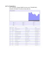
Page 35: ...4 2 7 4 Connections This Connections displays NIO200 real time active TCP UDP ICMP connection information for trouble shooting reference ...

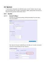
Page 36: ...ration SNMP Backup Flash Firmware and Reboot from the pull down list like below screen 4 3 1 System 4 3 1 1 General Settings This section provide general settings of NIO200 including Time Host name Time zone and NTP Click Sync with browser let NIO200 sync time with your computer And select country from the pull down list in the Timezone ...

Page 37: ...log configuration System log buffer size The size of log information Unit Kbytes External system log server The server address of external log server External system log server port The port number of external log server Log output level The output information of log including Debug Info Notice Warring Error Critical Alert and Emergency Cron Log Level The minimal level for cron messages to be logg...

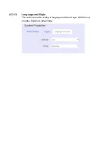
Page 38: ...4 3 1 3 Language and Style This section provides setting of language and WebUI style NIO200 only provides English as default style ...

Page 39: ...e 4 3 2 2 SSH Access Secure Shell SSH Enable NIO200 to be accessed via SSH based application This increase the security in configuration of NIO200 remotely Interface Select the interface Port Enter the port number for the communication via SSH Password authentication Enable Disable SSH password authentication ...

Page 40: ...SH Keys one per line for additional SSH public key authentication 4 3 3 Backup Flash Firmware To upgrade new firmware on device user may choose Backup Flash Firmware from Systme in tool bar as below 4 3 3 1 Upgrade Firmware To flash a new firmware image to NIO200 user may press the button of Flash image as below ...

Page 41: ...om the file browser Then WebUI displays the file checksum You can choose Proceed to start the upgrading Note After you click Proceed the DUT firmware will be upgraded with the file you selected and the upgrade progress will display like below ...

Page 42: ...l the WebUI should switch to the Login page User can also confirm the firmware image is successfully upgraded via Status Web page 4 3 3 2 Backup Configuration To back up the configuration file user may select the Generate archive button as below Then save it as a file in your PC To restore previous configuration user need to browse the backup file and then press Upload archive button as belwo ...

Page 43: ...sible 4 3 3 3 Reset to default To reset NIO200 to factory default configuration user will need to press Perform reset button as below Note The whole process may take several minutes to complete PLEASE DO NOT REBOOT OR POWER OFF THE DEVICE before the whole process being successfully done 4 3 4 Reboot Click the Perform reboot button will help to warm start the system After system finish reboot proce...

Page 44: ...t IP address When modifying the IP address user needs to input the IP address netmask gateway for this device and then click Save Apply to save this new IP address into flash and apply it immediately Note after apply new IP it would take several minutes to switch to the Status page via the new IP address Please enter the new IP address on browser again if the browser does not ...

Page 45: ...face when this is the only available interface otherwise the system will not be able to work Under such condition please press the button longer than 10 sec to get system back to factory default setting User can go on the configuration with defult IP address 192 168 1 1 WAN LAN Interface overview On this page you can configure the network interfaces You can bridge several interfaces by ticking the...

Page 46: ... server in your network or if you wish to assign a static IP address to NIO200WMR DHCP client When Dynamic IP DHCP is selected the DHCP client to be functional once this selection is made Unmanaged This Interface have no configuration interface or options PPP For old serial modem provided point to point link for NIO200WMR PPPoE For cable modem or ADSL user link NIO200WMR to your Internet provider ...

Page 47: ...This is used for advanced settings and configure strongly recommend user do not make change to this web page Physical Settings ...

Page 48: ...ace Normally only LAN interface need to enable bridge interfaces After enable bridge interfaces select interfaces to bridge Interface Select interfaces for your bridge group Select both the Ethernet adapter most likely eth0 1 eth1 and the wireless network DHCP Server General Setup ...

Page 49: ... IP or another DHCP server for your network interfaces Default is enable DHCP Advanced Settings Dynamic DHCP Dynamically allocate DHCP addresses for clients If disabled only clients having static leases will be served Force Force DHCP on this network even if another server is detected ...

Page 50: ...w includes channel SSID MAC address and security setting information Scan Scan can explore how many AP signals can be detected This is a good way to get the idea about how noisy the installation site is User can choose a channel which is less interference with other APs Add Add new virtual AP in the same radio interface You will see new interface after click add Disable Disable the radio interface...

Page 51: ...ed stations show wireless client connection information It includes the SSID wireless client connect wireless client MAC IP address RSSI signal strength and Tx Rx rate 4 4 2 3 Wireless configuration Please select network Wi Fi and click Edit to configure Radio0 or Radio1 The Device Configuration section covers physical settings of the radio hardware such as channel transmit power etc ...

Page 52: ...equency Select radio frequency and channel bandwidth for signal transmission For channel bandwidth please note you need to confirm AP client mode or mesh mode and which channel you will use Transmit Power Control the transmit power of a radio by selection of Transmission Power Advanced settings ...

Page 53: ...Only minor modifications of this value are recommended RTS CTS Threshold Default off RTS CTS Request to Send Clear to Send is the optional mechanism used by the 802 11 wireless networking protocol to reduce frame collisions introduced by the hidden node problem RTS CTS is an additional method to implement virtual carrier sensing in Carrier sense multiple access with collision avoidance CSMA CA Spe...

Page 54: ...P provides a basic level of security preventing unauthorized access to the network and encrypting data transmitted between wireless clients and an access point WEP uses static shared keys that are manually distributed to all clients that want to use the network WPA PSK Clients using WPA for authentication WPA2 PSK Clients using WPA2 for authentication WPA PSK WPA2 PSK Mixed Mode Clients using WPA ...

Page 55: ...fies the MAC address to block or allow traffic from 4 4 3 Mesh Advanced Mesh Advanced setting contains the important information about real Mesh connection path and Neighbor node signal strength and blocking status This is an advanced mechanism to keep Mesh network in stable and optimized condition 4 4 3 1 Mesh Advanced ...

Page 56: ...nal level higher than Block threshold the blocked Mesh link can be available again After continuous 5 seconds with signal level lower than Block threshold the active Mesh link will be blocked Low After continuous 10 seconds with signal level higher than Block threshold the blocked Mesh link can be available again After continuous 10 seconds with signal level lower than Block threshold the active M...

Page 57: ...I signal strength when refresh State display the current status is ESTAB established or BLOCKED blocked When BLOCKED implies the signal strength is too low to use in data forwarding Dest addr Next hop When Dest Destination MAC address and Next hop MAC address is the same the destination is available to connect directly from source Mesh node When the two MAC address is different the data forwarding...

Page 58: ...ive DHCP Leases Active DHCPv6 Leases Static Leases and Server Settings Scroll to the following screen in the DHCP and DNS window This screen displays the lease information to which DHCP server assigns automatically including Hostname IP address MAC address or DUID and Remaining Lease time DUID stands for the DHCP Unique Identifier Please look at the frame in red above The next category that users ...

Page 59: ...licking Add button a new entry with 4 blank input boxes will appear Allow users to fill in the information such as The MAC Address identifies the host the IPv4 Address specifies the fixed address to use and the Hostname is assigned as symbolic name to the requesting host Delete delete the followed entry Scroll to the screen identified as Server Settings category There are 4 tabs to select more opt...

Page 60: ...Domain required default value is checked Authoritative default value is checked 4 4 4 2 Resolve and Hosts Files 4 4 4 3 TFTP Settings By default TFTP server is not enabled ...

Page 61: ...4 4 4 4 Advanced Settings Max DHCP Leases default value is unlimited Max concurrent queries default value is 150 ...

Page 62: ...e For those device does not have hostname or does not resolve automatically users manually assign hostname IP pair to specific devices Add create a host entry hostname IP pair for a specific device For example Hostname Test Device IP address 192 168 1 251 Delete delete the followed host entry ...

Page 63: ...be reached over Such pair interface and gateway is called route For IPv4 network scroll down to Static IPv4 Routes screen as follows Add add an entry for route to an IPv4 network or host For example Target network 192 168 10 0 Netmask 255 255 255 0 NIO200WMR WAN IP 192 168 0 1 The route to be assigned will be wan for interface and 192 168 0 253 for gateway Leave Metric and MTU field to have defaul...

Page 64: ...elete delete a followed route entry For IPv6 network scroll down to Static IPv6 Routes screen as follows Add add an entry for route to an IPv6 network or host Clicking Add button has an entry as follows ...

Page 65: ...t Protocol IP network and measure the round trip time for messages sent from the originating host to a destination host and back The only required parameter is the name or IP address of the destination host Traceroute track the route packets taken from an IP network on their way to a given destination host The only required parameter is the name or IP address of the destination host Nslookup query...

Page 66: ...gs and Zones categories In the General Settings category there are 5 basic options for traffic control over interfaces Enable SYN flood protection default enabled Drop invalid packets default disabled Input default accept Output default accept and Forward default reject In the Zones category users create or edit zones over your network interfaces to control network traffic flow There 3 control but...

Page 67: ... or editing specific forwarding table allows remote computers on the Internet to connect to a specific computer or service within the private LAN In the New port forward category there is only one button for flow editing Add create a new flow entry for port forwarding among zones 4 4 8 3 Traffic Rules Clicking the Traffic Rules tab on the top of screen will appear the policy tables of 2 categories...

Page 68: ...ource IP used for outgoing traffic For example to map multiple WAN addresses to internal subnets can be added or edited Add and edit create a new entry with default values and edit at once if required Please remember clicking Save Apply button to activate the new settings 4 4 8 4 Custom Rules Custom rules allow you to execute arbitrary iptables commands which are not otherwise covered by the firew...

Reviews: