background image

NEXCOM International Co., Ltd.

NEXCOM International Co., Ltd.

Published January 2019

www.nexcom.com

Network


and


Communication


Solutions

Network Security Appliance 
NSA 7131

User Manual

Summary of Contents for NSA 7131

Page 1: ...NEXCOM International Co Ltd NEXCOM International Co Ltd Published January 2019 www nexcom com Network and Communication Solutions Network Security Appliance NSA 7131 User Manual ...

Page 2: ...xiii Ordering Information xiv Chapter 1 Product Introduction Overview 1 Key Features 1 Hardware Specifications 2 Knowing Your NSA 7131 3 Front Panel 3 Rear Panel 4 Chapter 2 Jumpers and Connectors Before You Begin 5 Precautions 5 Jumper Settings 6 Locations of the Jumpers and Connectors 7 Connector Pin Definitions 8 Internal Connectors 8 VGA Connector 8 SATA Connectors 8 USB 2 0 Header Reserved 9 ...

Page 3: ...Setup Installing a CompactFlash CF Card 18 Installing a CPU 19 Installing a DIMM Memory Module 21 Chapter 4 BIOS Setup About BIOS Setup 22 When to Configure the BIOS 22 Default Configuration 23 Entering Setup 23 Legends 23 BIOS Setup Utility 25 Main 25 Advanced 26 Intel RC Setup 36 Security 47 Boot 48 Save Exit 49 ...

Page 4: ...EXCOM International Co Ltd All other product names mentioned herein are registered trademarks of their respective owners Regulatory Compliance Statements This section provides the FCC compliance statement for Class A devices and describes how to keep the system CE compliant Declaration of Conformity FCC This equipment has been tested and verified to comply with the limits for a Class A digital dev...

Page 5: ... Polybrominated diphenyl Ethers PBDE 0 1 or 1 000ppm In order to meet the RoHS compliant directives NEXCOM has established an engineering and manufacturing task force in to implement the introduction of green products The task force will ensure that we follow the standard NEXCOM development procedure and that all the new RoHS components and new manufacturing processes maintain the highest industry...

Page 6: ...ective products making sure it is durable enough to be resistant against further damage and deterioration during transportation In case of damages occurred during transportation the repair is treated as Out of Warranty Any products returned by NEXCOM to other locations besides the customers site will bear an extra charge and will be billed to the customer Repair Service Charges for Out of Warranty...

Page 7: ...nd power supply are inconsistent with these instructions or the instructions for accessory modules contact the supplier to find out how you can ensure that your computer meets safety and regulatory requirements Cautions Electrostatic discharge ESD can damage system components Do the described procedures only at an ESD workstation If no such station is available you can provide some ESD protection ...

Page 8: ...e the soft metal or plastic parts of the connectors Safety Information Before installing and using the device note the following precautions Read all instructions carefully Do not place the unit on an unstable surface cart or stand Follow all warnings and cautions in this manual When replacing parts ensure that your service technician uses parts specified by the manufacturer Avoid using the system...

Page 9: ...ment For safety reasons the equipment should be opened only by skilled person 14 If one of the following situations arises get the equipment checked by service personnel a The power cord or plug is damaged b Liquid has penetrated into the equipment c The equipment has been exposed to moisture d The equipment does not work well or you cannot get it to work according to the user s manual e The equip...

Page 10: ...rsion application software etc A complete description of the problem The exact wordings of the error messages Warning 1 Handling the unit carry the unit with both hands and handle it with care 2 Maintenance to keep the unit clean use only approved cleaning products or clean with a dry cloth 3 CompactFlash Turn off the unit s power before inserting or removing a CompactFlash storage card Convention...

Page 11: ...hung Office 16F No 250 Sec 2 Chongde Rd Beitun Dist Taichung City 406 R O C Tel 886 4 2249 1179 Fax 886 4 2249 1172 Email sales nexcom com tw www nexcom com tw NexCOBOT Taiwan Co Ltd 13F No 916 Chung Cheng Rd ZhongHe District New Taipei City 23586 Taiwan R O C Tel 886 2 8226 7796 Fax 886 2 8226 7792 Email sales nexcom com tw www nexcom com tw GreenBase Technology Corp 13F No 922 Chung Cheng Rd Zho...

Page 12: ...mingzun Plaza Bldg 1 No 609 Yunlin East Rd Shanghai 200062 China Tel 86 21 5278 5868 Fax 86 21 3251 6358 Email sales nexcom cn www nexcom cn NEXCOM Surveillance Technology Corp Floor 5 Building C ZhenHan Industrial Zone GanKeng Community Buji Street LongGang District ShenZhen 518112 China Tel 86 755 8364 7768 Fax 86 755 8364 7738 Email steveyang nexcom com tw www nexcom cn NEXCOM United System Ser...

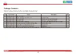
Page 13: ... Foot Kang Yang RF20 5 4P 19 8x18x5 0mm 4 3 6012200052X00 PE Zipper Bag 8 170x240mm w China RoHS Symbol 1 4 6012200053X00 PE Zipper Bag 3 100x70mm w China RoHS Symbol 1 5 6023309081X00 Cable EDI 232091081804 RS COM Port DB9 Female to RJ45 8P8C L 1800mm 1 6 50311F0109X00 Flat Head Screw Long Fei F6 32Tx5 Nylok Black F6 32Tx5 Black Nylok 16 7 50311F0162X00 Round Head Screw GW Washer Long Fei P4x8 is...

Page 14: ...SFP None None All Slot NX 142F 10S20142F01X0 XL710 BM1 PCIe x8 4 SFP 2 bypass None All Slot NX 120F 10S20120F00X0 X710 BM2 PCIe x8 2 SFP None One All Slot NI 140F 10SK000NI02X0 i350AM4x1 PCIe x8 4 SFP None None All Slot NI 180F 10S10180F01X0 i350AM4x2 PCIe x8 8 SFP None One All Slot NI 142C 10SK000NI03X0 i350AM4x1 PCIe x8 4 Copper 2 bypass None All Slot NI 180C 10S10180C01X0 i350AM4x2 PCIe x8 8 Co...

Page 15: ...NSA 7131 User Manual Chapter 1 Product Introduction Chapter 1 Product Introduction Key Features Dual Intel Xeon processor E5 2600 v4 v3 product family Support DDR4 1866 2133 ECC REG Support 4 x 3 5 swappable HDD bays Overview Support LCD module Four LAN module slots ...

Page 16: ...port Intel i350 Intel XL710 copper fiber ports Support 10 100 1000 10G link speed LAN bypass Please see LAN module list information I O Interface Front 1 x Management port LAN chip Intel i210 2 x USB 2 0 ports 1 x RJ45 type console port 4 x PCIe Gen 3 LAN module slots x8 x8 x4 x4 Devices 1x onboard CF card socket Power Input 550W 1 1 CRPS redundant power supply Chassis Dimensions Chassis dimension...

Page 17: ...nt LAN HDD Bays LAN Module Slots HDD Bays Four 3 5 HDD swappable bays LAN Module Slots Four LAN module slots LED Indicators Indicates the power status and storage drive activity of the system Console Port Used to connect RJ45 type console port USB Ports Used to connect USB 2 0 1 1 devices Management LAN Ports 2 LAN ports used for managing the system Reset Button Press to restart the system LED Ind...

Page 18: ...ed 4 NSA 7131 User Manual Chapter 1 Product Introduction Rear Panel Power Switch AC Power Sockets Power Switch Press to power on or power off the system AC Power Sockets Dual redundant power supply sockets plug an AC power cord here before turning on the system ...

Page 19: ...rself before touching any internal components by touching a metal object Static electricity can damage many of the electronic components Humid environments tend to have less static electricity than dry environments A grounding strap is warranted whenever danger of static electricity exists Precautions Computer components and electronic circuit boards can be damaged by discharges of static electric...

Page 20: ... jumpers ensure that the jumper caps are placed on the correct pins When the jumper cap is placed on both pins the jumper is short If you remove the jumper cap or place the jumper cap on just one pin the jumper is open Refer to the illustrations below for examples of what the 2 pin and 3 pin jumpers look like when they are short on and open off Two Pin Jumpers Open Left and Short Right Three Pin J...

Page 21: ...4 287 144 287 220 77 1 2 145 146 1 1 1 4 4 A2 A1 B1 B2 A48 H20 H22 A49 B49 B48 2 145 H14 H17 146 1 2 145 146 1 2 145 146 220 77 220 77 220 77 144 287 144 H4 H5 5 3 1 3 1 3 1 3 1 3 1 3 8 3 1 1 16 H2 3 DIMM Slot5 DIMM Slot6 DIMM Slot8 DIMM Slot7 B49 1 6 B25 B1 B11 B12 B49 H18 B1 B11 B12 B49 H21 1 4 1 1 3 1 3 1 1 2 2 19 49 3 3 12 1 4 5 8 H11 H1 24 H16 1 1 1 13 3 1 1 5 1 7 1 7 1 7 1 7 1 7 1 7 1 7 1 7 ...

Page 22: ...er 2 0mm pitch Connector location VGACONN1 SATA Connectors Connector type Standard Serial ATA 7P 1 27mm SATA M 180 Connector location SATA1 to SATA8 Pin Definition Pin Definition 1 GND 2 TXP 3 TXN 4 GND 5 RXN 6 RXP 7 GND Pin Definition Pin Definition 1 DACROA_B 2 DACGOA_B 3 DACBOA_B 4 NC 5 GND 6 GND 7 GND 8 GND 9 VGA_VCC 10 GND 11 NC 12 DDC_DATAO_B 13 AHSYNCO_B 14 AVSYNCO_B 15 DDC_CLKO_B 16 NC 1 2...

Page 23: ...ors USB 2 0 Header Reserved Connector type 1x6 6 pin header 2 0mm pitch Connector location J4 LCM Header Connector type 1x6 6 pin header 2 0mm pitch Connector location J6 1 6 1 6 Pin Definition Pin Definition 1 5V 2 DN2 3 DP2 4 DN3 5 DP3 6 GND Pin Definition Pin Definition 1 TX 2 RX 3 GND 4 5V 5 LED_KR_N 6 LED_KG_N ...

Page 24: ... CPU Fan Connector Connector type 1x4 4 pin wafer Connector location FAN1 1 4 Pin Definition Pin Definition 1 GND 2 P12V_CPU 3 FAN_TACH 4 FAN_PWM ATX 4 pin Connector Reserved Connector type 1x4 4 pin header 5 08mm pitch Connector location CON4 CON5 CON6 and CON7 1 4 Pin Definition Pin Definition 1 P12V 2 GND 3 GND 4 P5V ...

Page 25: ...B01_C 2 USB2_L_DN1 3 USB2_L_DP1 4 GND 5 USB3_L_RX_N2 6 USB3_L_RX_P2 7 GND 8 USB3_L_TX_N2 9 USB3_L_TX_P2 10 GND 11 USB2_L_DP0 12 USB2_L_DN0 13 GND 14 USB3_L_TX_P1 15 USB3_L_TX_N1 16 GND 17 USB3_L_RX_P1 18 USB3_L_RX_N1 19 PV5_USB01_C 20 NC 11 10 20 1 1 4 5 8 Pin Definition Pin Definition 1 GND 2 GND 3 GND 4 GND 5 P12V 6 P12V 7 P12V 8 P12V 8 pin ATX Power Connectors Connector type 2x4 8 pin boxed hea...

Page 26: ...efinition 1 ATX_P3V3 2 ATX_P3V3 3 GND 4 P5V 5 GND 6 P5V 7 GND 8 PW OK 9 P5VSB 10 P12V 11 P12V 12 ATX_P3V3 13 ATX_P3V3 14 12V 15 GND 16 PS ON 17 GND 18 GND 19 GND 20 RES 5V 21 P5V 22 P5V 23 P5V 24 GND 1 12 13 24 1 12 24 13 COM Port Header Reserved Connector type 2x5 10 pin header 2 0mm pitch Connector location CN1 2 1 10 9 Pin Definition Pin Definition 1 SP_DCD2 2 SP_RXD2 3 SP_TXD2 4 SP_DTR2 5 GND ...

Page 27: ... 10 pin header 2 0mm pitch Connector location JP1 1 9 2 10 Pin Definition Pin Definition 1 P5V 2 GND 3 SIO_GP32 4 SIO_GP06 5 SIO_GP03 6 SIO_GP07 7 SIO_GP04 8 SIO_GP76 9 SIO_GP05 10 SIO_GP77 PMBUS Header Connector type 1x5 5 pin header 2 54mm pitch Connector location JPSMI1 Pin Definition Pin Definition 1 PMBUS CLK 2 PMBUS DATA 3 PMBUS ALERT Reserve 4 GND 5 NC 1 5 ...

Page 28: ...national Co Ltd All Rights Reserved 14 NSA 7131 User Manual Chapter 2 Jumpers and Connectors PSU TTL Header Connector type 1x3 3 pin header 2 0mm pitch Connector location JP18 1 3 Pin Definition 1 PSU_status1 2 PSU_status2 3 GND ...

Page 29: ...V A9 3 3V B9 NC A10 3 3V B10 P3V3AUX A11 PRSNT B11 WAKE A12 GND B12 BYPASS GATE Enable A13 CLK_P B13 GND A14 CLK_N B14 TX0P A15 GND B15 TX0N A16 RX0P B16 GND Pin Definition Pin Definition A17 RX0N B17 NC A18 GND B18 GND A19 BYPASS_A Enable B19 TX1P A20 GND B20 TX1N A21 RX1P B21 GND A22 RX1N B22 GND A23 GND B23 TX2P A24 GND B24 TX2N A25 RX2P B25 GND A26 RX2N B26 GND A27 GND B27 TX3P A28 GND B28 TX3...

Page 30: ... Definition Pin Definition A33 BYPASS_D Enable B33 TX4P A34 GND B34 TX4N A35 RX4P B35 GND A36 RX4N B36 GND A37 GND B37 TX5P A38 GND B38 TX5N A39 RX5P B39 GND A40 RX5N B40 GND A41 GND B41 TX6P A42 GND B42 TX6N A43 RX6P B43 GND A44 RX6N B44 GND A45 GND B45 TX7P A46 GND B46 TX7N A47 RX7P B47 GND A48 RX7N B48 NC A49 GND B49 GND ...

Page 31: ...Connector 2 x USB 3 0 2 x USB 2 0 8 x SATA3 CNN 1 x CF Card Socket 1 x VGA Pin header 1 x Console port 1x5 header 1 x GPIO Pin header 2x5 PCI E x8 8x DDR4 Socketsw 4 Channels Up to 4 LAN Modules Internal Access PCIe x1 2x PCIe x1 NCN7131 IO Board 1 x LCM 2 x USB 2 0 Port 1 x Console Port 1 x SW Bottom 2 x MGMT LAN Port 4 x GPIO LED PCIe x4 Internal Access LAN LAN LAN LAN ...

Page 32: ...ed 18 NSA 7131 User Manual Chapter 3 System Setup 2 Insert the CF module until it is completely seated into the slot Chapter 3 System Setup Installing a CompactFlash CF Card CF Slot CF Module 1 With the chassis cover removed locate the CF slot on the motherboard ...

Page 33: ... Setup Installing a CPU 1 Locate the CPU socket on the motherboard 2 Unlock the socket by pushing the two load levers down moving them sideways until they are released from the retention tabs then lift the load levers up and remove the CPU protective cap Load Lever Load Lever Retention Tab Retention Tab ...

Page 34: ...PU socket shown on the photo Handle the CPU by its edges and avoid touching the pins The CPU will fit in only one orientation and can easily be inserted without exerting any force CAUTION CAUTION CAUTION 4 Close the load plate and then hook the load levers under the retention tabs Do not force the CPU into the socket Forcing the CPU into the socket may bend the pins and damage the CPU CAUTION CAUT...

Page 35: ... a DIMM Memory Module 1 Locate the DIMM sockets on the motherboard 3 Insert the module into the socket at an 90 degree angle Apply firm even pressure to each end of the module until it slips into the socket 4 While pushing the module into position the lock will close automatically 2 Release the locks on the DIMM sockets ...

Page 36: ... is configured with the values found in CMOS With easy to use pull down menus you can configure such items as Hard drives diskette drives and peripherals Video display type and display options Password protection from unauthorized use Power management features The settings made in the setup program affect how the computer performs It is important therefore first to try to understand all the setup ...

Page 37: ...ntered the error will be reported in one of two different ways If the error occurs before the display device is initialized a series of beeps will be transmitted If the error occurs after the display device is initialized the screen will display the error message Powering on the computer and immediately pressing allows you to enter Setup Legends Key Function Moves the highlight left or right to se...

Page 38: ...up screen it indicates that there are more available fields not shown on the screen Use the up and down arrow keys to scroll through all the available fields Submenu When appears on the left of a particular field it indicates that a submenu which contains additional options are available for that field To display the submenu move the highlight to that field and press ...

Page 39: ...alues F3 Optimized Defaults F4 Save Reset ESC Exit Set the Date Use Tab to switch between Date elements BIOS Information BIOS Vendor Core Version Compliancy Project Version Build Date and Time Access Level Memory Information Total Memory System Date System Time American Megatrends 5 11 UEFI 2 4 PI 1 3 G131 0 30 x64 11 21 2017 17 31 07 Administrator 4096 MB Mon 08 20 2018 13 14 40 Access Level Disp...

Page 40: ... NCT6776 Super IO Configuration Hardware Monitor AST SEC Super IO Configuration Serial Port Console Redirection PCI Subsystem Settings Network Stack Configuration CSM Configuration USB Configuration Security Boot Save Exit NCT6776 Super IO Configuration This section is used to configure the I O functions supported by the onboard Super I O chip Super IO Chip Displays the Super I O chip used on the ...

Page 41: ...xit Enable or Disable Serial Port COM Serial Port 1 Configuration Serial Port Device Settings Change Settings Enabled IO 3F8h IRQ 4 Auto Serial Port 2 Configuration This section is used to configure serial port 2 Serial Port Enables or disables the serial port Change Settings Selects an optimal setting for the Super IO device Advanced Version 2 17 1249 Copyright C 2017 American Megatrends Inc Apti...

Page 42: ...s Values F3 Optimized Defaults F4 Save Reset ESC Exit Pc Health Status CPU temperature THR1 temperature THR2 temperature CPU Fan Speed CN2 Fan Speed CN3 Fan Speed CN4 Fan Speed CN5 Fan Speed CN6 Fan Speed VCORE PVDDQ PVCCIO P3V3 P5V P12V 64 C 42 C 43 C 3658 RPM N A N A N A N A N A 1 794 V 1 184 V 1 040 V 3 288 V 4 960 V 12 096 V AST SEC Super IO Configuration This section is used to configure the ...

Page 43: ... Settings Legacy Console Redirection Legacy Console Redirection Settings Serial Port for Out of Band Management Windows Emergency Management Services EMS Console Redirection Console Redirection Settings Enabled Disabled Disabled Enabled Console Redirection Enables or disables the console redirection Serial Port 2 Configuration This section is used to configure serial port 2 Serial Port Enables or ...

Page 44: ...to 1 or more bytes Data Bits The options are 7 and 8 Bits Per Second Selects the serial port transmission speed The speed must match the other side Long or noisy lines may require a lower speed Parity A parity bit can be sent with the data bits to detect some transmission errors Even Parity bit is 0 if the number of 1 s in the data bits is even Odd Parity bit is 0 if number of 1 s in the data bits...

Page 45: ...cond Flow Control Data Bits Parity Stop Bits COM3 VT UTF8 115200 None 8 None 1 Out of Band Mgmt Port Configures the out of band management port Microsoft Windows Emergency Management Services EMS allows for remote management of a Windows Server OS via a serial port Terminal Type ANSI Extended ASCII character set VT100 ASCII character set VT100 Extends VT100 to support color function keys etc VT UT...

Page 46: ...y redirection of legacy OS and legacy OPROM messages PCI Subsystem Settings This section is used to configure the PCI Advanced Version 2 17 1249 Copyright C 2017 American Megatrends Inc Aptio Setup Utility Copyright C 2017 American Megatrends Inc Select Screen Select Item Enter Select Change Opt F1 General Help F2 Previous Values F3 Optimized Defaults F4 Save Reset ESC Exit Enables or Disables 64b...

Page 47: ...axed Ordering Enables or disables the PCI Express device s relaxed ordering Extended Tag When this function is enabled it allows a device to use 8 bit tag field as a request No Snoop Enables or disables the PCI Express device s no snoop option Maximum Payload Selects the maximum TLP payload size of the PCI Express devices Network Stack Configuration This section is used to configure the network st...

Page 48: ...ESC Exit Enable Disable CSM Support Compatibility Support Module Configuration CSM Support CSM16 Module Version Option ROM execution Network Storage Video Other PCI devices Enabled 07 79 Do not launch Legacy Legacy UEFI CSM Support This field is used to enable or disable CSM support if Auto option is selected based on OS CSM will be enabled or disabled automatically Network Enables or disables the...

Page 49: ...nected Disable Keeps USB devices available only for EFI applications XHCI Hand off This is a workaround for OSs that does not support XHCI hand off The XHCI ownership change should be claimed by the XHCI driver USB Configuration This section is used to configure the USB EHCI Hand Off This is a workaround for OSs that does not support EHCI hand off The EHCI ownership change should be claimed by the...

Page 50: ...Reset ESC Exit Change Per Socket Settings Processor Configuration Per Socket Configuration Processor Socket Socket 0 Processor ID 000406F1 Processor Frequency 2 400GHz Processor Max Ratio 18H Processor Min Ratio 0CH Microcode Revision 0B000014 L1 Cache RAM 896KB L2 Cache RAM 3584KB L3 Cache RAM 35840KB Processor 0 Version Intel R Xeon R CPU E5 2680 v4 2 40GHz Hyper Threading ALL Enable Execute Dis...

Page 51: ...elect Change Opt F1 General Help F2 Previous Values F3 Optimized Defaults F4 Save Reset ESC Exit Select Screen Select Item Enter Select Change Opt F1 General Help F2 Previous Values F3 Optimized Defaults F4 Save Reset ESC Exit Number of Cores to Enable 0 means all cores 14 Cores available CPU Socket 0 Configuration CPU Socket 0 Configuration Cores Enabled IOT Cfg Cbo Bitmap 0 Per Socket Configurat...

Page 52: ...elp F2 Previous Values F3 Optimized Defaults F4 Save Reset ESC Exit Maximum Memory Frequency Selections in Mhz Do not select Reserved Integrated Memory Controller iMC Memory Frequency Memory Topology IntelRCSetup Auto Memory Topology Detects and displays the information on the memory installed Save Exit Advanced Security Boot Main Version 2 17 1249 Copyright C 2017 American Megatrends Inc Aptio Se...

Page 53: ...ht C 2017 American Megatrends Inc Select Screen Select Item Enter Select Change Opt F1 General Help F2 Previous Values F3 Optimized Defaults F4 Save Reset ESC Exit Selects PCIe port Bifurcation for selected slot s IOU2 IIO PCIe Port 1 IOU0 IIO PCIe Port 2 IOU1 IIO PCIe Port 3 No PCIe port active E Socket 0 PcieD00F0 Port 0 DMI Socket 0 PcieD01F0 Port 1A Socket 0 PcieD02F0 Port 2A Socket 0 PcieD02F...

Page 54: ...ht C 2017 American Megatrends Inc Aptio Setup Utility Copyright C 2017 American Megatrends Inc Select Screen Select Item Enter Select Change Opt F1 General Help F2 Previous Values F3 Optimized Defaults F4 Save Reset ESC Exit In auto mode the BIOS will remove the EXP port if there is no device or errors on that device and the device is not HP capable Disable is used to disable the port and hide its...

Page 55: ...rface Configuration IIOAPIC for IIO 0 Intel VT for Directed I O VT d Save Exit Advanced Security Boot Main Version 2 17 1249 Copyright C 2017 American Megatrends Inc Aptio Setup Utility Copyright C 2017 American Megatrends Inc Select Screen Select Item Enter Select Change Opt F1 General Help F2 Previous Values F3 Optimized Defaults F4 Save Reset ESC Exit Enable Disable Intel Virtualization Technol...

Page 56: ...tion PCH sSATA Configuration PCH SATA Configuration USB Configuration IntelRCSetup PCH Devices Save Exit Advanced Security Boot Main Version 2 17 1249 Copyright C 2017 American Megatrends Inc Aptio Setup Utility Copyright C 2017 American Megatrends Inc Select Screen Select Item Enter Select Change Opt F1 General Help F2 Previous Values F3 Optimized Defaults F4 Save Reset ESC Exit Enable Disable SM...

Page 57: ...F3 Optimized Defaults F4 Save Reset ESC Exit PCI Express Root Port 2 Settings LAN PCIE Port used PCI Express Root Port 2 PCI Express Root Port 3 PCI Express Root Port 4 PCI Express Root Port 5 IntelRCSetup None PCI Express Root Port 2 Save Exit Advanced Security Boot Main Version 2 17 1249 Copyright C 2017 American Megatrends Inc Aptio Setup Utility Copyright C 2017 American Megatrends Inc Select ...

Page 58: ...y Copyright C 2017 American Megatrends Inc Select Screen Select Item Enter Select Change Opt F1 General Help F2 Previous Values F3 Optimized Defaults F4 Save Reset ESC Exit Enable or Disable SATA Controller PCH sSATA Configuration sSATA Controller Configure sSATA as sSATA Port 0 Port 0 Hot Plug SATA Device Type sSATA Port 1 Port 1 Hot Plug SATA Device Type sSATA Port 2 Port 2 Hot Plug SATA Device ...

Page 59: ...A Controller PCH SATA Configuration SATA Controller Configure SATA as SATA Port 0 Port 0 SATA Device Type SATA Port 1 Port 1 Hot Plug SATA Device Type SATA Port 2 Port 2 Hot Plug SATA Device Type SATA Port 3 Port 3 Hot Plug SATA Device Type IntelRCSetup Enabled AHCI Not Installed Enabled Hard Disk Drive Not Installed Enabled Disabled Hard Disk Drive Not Installed Enabled Disabled Hard Disk Drive N...

Page 60: ... SATA Device Type SATA Port 3 Port 3 Hot Plug SATA Device Type SATA Port 4 Port 4 Hot Plug SATA Device Type SATA Port 5 Port 5 Hot Plug SATA Device Type IntelRCSetup Not Installed Enabled Disabled Hard Disk Drive Not Installed Enabled Disabled Hard Disk Drive Not Installed Enabled Disabled Hard Disk Drive Not Installed Enabled Disabled Hard Disk Drive Not Installed Enabled Disabled Hard Disk Drive...

Page 61: ...ot be shown IntelRCSetup Enabled ByPass Auto Detect Enables or disables automatic LAN Bypass function Security This section is used to configure the processor and chipset settings Advanced IntelRCSetup Main Version 2 17 1249 Copyright C 2017 American Megatrends Inc Aptio Setup Utility Copyright C 2017 American Megatrends Inc Select Screen Select Item Enter Select Change Opt F1 General Help F2 Prev...

Page 62: ...faults F4 Save Reset ESC Exit Number of seconds to wait for setup activation key 65535 0xFFFF means indefinite waiting Boot Configuration Setup Prompt Timeout Bootup NumLock State Quiet Boot Boot mode select FIXED BOOT ORDER Priorities Boot Option 1 Boot Option 2 Boot Option 3 Boot Option 4 Boot Option 5 Boot Option 6 Boot Option 7 Boot Option 8 USB Key Drive BBS Priorities On Disabled LEGACY USB ...

Page 63: ... then press Enter A dialog box will appear Confirm by selecting Yes You can also press F4 to save and exit Setup Discard Changes and Exit To exit the Setup utility without saving the changes select this field then press Enter You may be prompted to confirm again before exiting You can also press ESC to exit without saving the changes Save Changes and Reset To save the changes and reset select this...

Reviews: