background image

IDD HDD Auto-Detection

If you want the Setup Utility to automatically detect and configure a hard disk drive
on the IDE channel, press <

Enter

> while this item is highlighted.

If your system has an IDE hard drive, you can use this utility to detect its param-
eters and enter them into the Standard CMOS Setup automatically.
If the auto-detected parameters displayed do not match the ones that should be
used for your hard drive, do not accept them.  Press the <

N

> key to reject the

values and enter the correct ones manually in the Standard CMOS Setup screen.
(

Note: 

If you are setting up a new hard disk drive that supports LBA mode, more

than one line will appear in the parameter box. Choose the line that lists 

LBA 

for an

LBA drive.)
Do not choose 

Large

 or 

Normal

 if the hard disk drive is already fully formatted

when you installed it.  Select the mode that was used to format it.

IDE Primary/Secondary Master/Slave

If you leave this item at 

Auto

, the system will automatically detect and configure

any IDE devices it finds. If it fails to find a hard disk, change the value to 

Manual

and then manually configure the drive by entering the characteristics of the drive in
the items below:

         Capacity                      approximate hard disk drive capacity
         Cylinder                      number of cylinders
         Head                            number of heads
         Precomp                      write precompensation cylinder
        Landing Zone             landing zone

         Sector                          number of sectors

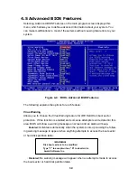
                                        Figure 4-3 :  BIOS- IDE Primary Master

31

Summary of Contents for PEAK 715 Series

Page 1: ...ww nexcom com PEAK 715 HT Single Board Computer User s Manual PEAK715 HT Single Board Computer is compatible with multi segmented backplanes and power supplies 2003 08 Edition The Digital Infrastructure ...

Page 2: ...ames mentioned herein are registered trademarks of their respec tive owners Regulatory Compliance Statements This section provides the FCC compliance statement for Class A devices and describes how to keep the system CE compliant FCC Compliance Statement for Class A Devices The product s described in this user s guide has been tested and proved to com ply with the limits for a Class A digital devi...

Page 3: ...em Memory 17 3 2 Installing DIMM 18 3 3 Change CPU 20 3 4 Installing the Fan Heatsink 21 Chapter 4 Award BIOS Setup 24 4 1 Entering Setup 25 4 2 The Main Menu 26 4 3 1 Getting Help 28 4 3 2 Control Keys 29 4 4 Standard CMOS Features 30 4 5 Advanced BIOS Features 34 4 6 Advanced Chipset Features 38 4 7 Integrated Peripherals 41 4 8 Power Management Setup 44 4 9 PnP PCI Configurations 47 4 10 PC Hea...

Page 4: ... 4 1 BIOS Control Keys 29 Table B 1 Watchdog Timer Character and Function 66 Table B 2 WDT Control Register Bit Definition 67 Table B 3 WDT Control Register Initial Value 67 Figures Figure 1 1 PEAK 715VL2G HT Board Layout 10 Figure 2 1 How to Set Jumpers 13 Figure 2 2 Jumper Locations 14 Figure 3 1 How to Install DIMM 1 18 Figure 3 2 How to Install DIMM 2 18 Figure 3 3 How to Install DIMM 3 19 Fig...

Page 5: ...ter 31 Figure 4 4 BIOS Advanced BIOS Features 34 Figure 4 5 BIOS Advanced Chipset Features 38 Figure 4 6 BIOS Integrated Peripherals 41 Figure 4 7 BIOS Power Management Setup 44 Figure 4 8 BIOS PnP PCI Configurations 47 Figure 4 9 BIOS PC Health Status 49 Figure 4 10 BIOS Frequency Voltage Control 50 4 ...

Page 6: ...Chapter 1 General Information 5 ...

Page 7: ... Dual Intel 82551QM Ethernet controllers for PEAK 715 VL2 HT Intel 82551QM x 1 and Intel 82540EM Gigabit Ethernet controller x1 for PEAK 715VL2G HT o USB 2 0 port 480 Mbps x 4 1 2 Specification System Architecture Full size SBC with PCI ISA gold plated DIMMs PCI V2 2 compliant PICMG 1 0 Rev 2 0 compliant CPU Support Intel Pentium 4 Celeron processor with 256K 512K L2 cache on die Intel Pentium 4 M...

Page 8: ...Board VGA Intel 82845GV GMCH chipset integrated with Graphics controller Hardware motion compensation assist for software MPEG DVD decode 64MB VGA share Memory Fully PC 98 and PC 99 Compliant 15 pin CRT connector x1 On Chip I O ICH4 On board USB port 480 Mbps x 4 via NEXCOM s proprietary USB cable Ultra ATA100 66 33 support 40 pin connector x 2 On Board I O ITE 8712F A Super I O SIO x 2 with 2 x 1...

Page 9: ...re and Vcc5V Stand By Monitoring CPU fan speed Monitoring CPU system temperatures ACPI Function Only when 3 pin power cable is connected to backplane and thus connected to ATX power source Soft power off Power on by LAN Power on by Keyboard Power on by Ring Real Time Clock On chip RTC with one back up external Li battery Watchdog Timer Watchdog timeout programmable from 1 2 4 8 to 128 seconds PCI ...

Page 10: ... ing table compares their main features 9 s t e s p i h C y r o m e M s t e s p i h C A G V d e t a r g r e t n I M Q 1 5 5 2 8 l e t n I t e n r e h t E 0 0 1 0 1 M E 0 4 5 2 8 l e t n I t e n r e h t E t i b a g i G G 2 L V 5 1 7 K A E P T H V G 5 4 8 l e t n I g n i p p e t S B 3 3 3 R D D s e Y t r o p 1 t r o p 1 T H 2 L V 5 1 7 K A E P V G 5 4 8 l e t n I g n i p p e t S B 3 3 3 R D D s e Y ...

Page 11: ...e board in case it lacks any One PEAK 715 HT Quick Reference Guide the sticker printed with jumper info attached on the white box which packs the mainboard One 50CM Cable JST 2 5mm 3 pin to 3 pin 5V standby ATX Power on Cable One Y Cable for Keyboard and Mouse One 180 mm AUX Power Cable for J2 One Cable Set FDD x1 SIO PIO x1 SIO x1 Keyboard x1 IDE66 x1 One USB Cable with Bracket One Driver Manual ...

Page 12: ...Chapter 2 Jumper Setting 11 ...

Page 13: ...1 J 1 M O C 4 1 J r o t c e n n o C B S U 5 1 J e p y T h s a l F t c a p m o C 6 1 J r o t c e n n o C r e w o P X T A 7 1 J e d o M r e w o P 8 1 J O I r e p u S t r o P O I P G 9 1 J k c o l y e K 0 2 J r o t c e n n o C R I 1 2 J r o t c e n n o C y p p o l F 2 2 J t r o P O I P 3 2 J r o t c e n n o C d r a o b y e K l a n r e t x E 4 2 J r o t c e n n o C e s u o M d r a o b y e K 5 2 J r o ...

Page 14: ...s SHORT If you remove the jumper cap or place the jumper cap on just one pin the jumpr is OPEN Please see the following illustrations Figure 2 1 How to Set Jumpers 13 The illustrations on the right show a 2 pin jumper When the jumper cap is placed on both pins the jumper is SHORT If you remove the jumper cap or place the jumper cap on just one pin the jumper is OPEN Open Off Short On These illustr...

Page 15: ...2 3 Locating Jumpers The illustration below shows the location of the mainboard jumpers Figure 2 2 Jumper Locations 14 Pin 1 Pin 1 Pin 1 Pin 1 Pin 1 ...

Page 16: ...urning on the power clear procedure is completed O N N I P n o i t p i r c s e D 2 1 l a m r o N 3 2 r a e l C 2 5 Setting CPU Type JP3 o N N I P n o i t p i r c s e D C N n o r e l e C 4 P 2 1 M 4 P Note Please turn off the power and change CPU before setting this jumper o N N I P n o i t p i r c s e D 2 1 e v a l S 3 2 r e t s a M o N N I P n o i t p i r c s e D 2 1 t r o h S r e w o P T A 3 2 n...

Page 17: ...Chapter 3 Capability Expanding 16 ...

Page 18: ... banks Please be noted that the PEAK 715 HT Series support Double Data DDR333 SDRAM Configurations using different brands of memory modules are not recommended DIMM 1 DIMM2 Total Memory 128MB Empty 128MB Empty 128MB 128MB 128MB 128MB 256MB 256MB Empty 256MB Empty 256MB 256MB 256MB 256MB 512MB 512MB Empty 512MB Empty 512MB 512MB 512MB 512MB 1024MB 1024MB Empty 1024MB Empty 1024MB 1024MB 1024MB 1024...

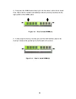
Page 19: ...e the two handles of the DIMM sockets are in the open position i e the handles stay outward Figure 3 1 How to Install DIMM 1 2 Slowly slide the DIMM modules along the plastic guides in the both ends of the socket Figure 3 2 How to Install DIMM 2 18 ...

Page 20: ...two handles automatically locked the memory modules into the right position of the DIMM socket 4 To take away the memory module just push the both handles outward the memory module will be ejected by the mechanism in the socket Figure 3 3 How to Install DIMM 3 Figure 3 4 How to Install DIMM 4 19 ...

Page 21: ...fully lift the existing CPU up to remove it from the socket 2 Place the new CPU on the middle of the socket orienting its beveled corner to line up with the socket s beveled corner Make sure the pins of the CPU fit evenly to the socket openings Replace the handling bar to fasten the CPU to the socket Figure 3 5 How to Change CPU 20 ...

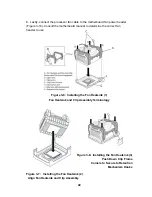
Page 22: ...eatsink to rotate or twist on the processor s integrated heat spreader Securing the fan heatsink while closing the clip levers will ensure the thermal interface material is not damaged and the pro cessor will operate correctly Follow these steps for closing the clip levers and ensuring the thermal interface material is not damaged a Make sure to close the clips levers in opposing directions one at...

Page 23: ...al to determine the correct fan header to use Fan Heatsink and Clip Assembly Terminology Align Fan Heatsink and Clip Assembly Figure 3 8 Installing the Fan Heatsink 3 Push Down Clip Frame Corners to Secure to Retention Mechanism Hooks Figure 3 6 Installing the Fan Heatsink 1 Figure 3 7 Installing the Fan Heatsink 2 22 ...

Page 24: ...sink 5 Close Clip Levers Close Clip Lever 1 One at a Time While Holding the Topside of Fan Heatsink A Figure 3 9c Installing the Fan Figure 3 10 Installing the Fan Heatsink 6 Heatsink 7 Close Clip Lever 2 Connect Fan Cable to Motherboard While Holding the Topside of Fan Heatsink B ...

Page 25: ...Chapter 4 Award BIOS Setup 24 ...

Page 26: ... the bottom of the screen during the POST Power On Self Test press Del key or simultaneously press Ctrl Alt and Esc keys TO ENTER SETUP BEFORE BOOT PRESS CTRL ALT ESC OR DEL KEY If the message disappears before you respond and you still wish to enter Setup restart the system to try again by turning it Off then On or pressing the RESET button on the system case You may also restart by simultaneousl...

Page 27: ...ress Enter to accept or enter the sub menu Figure 4 1 BIOS Main Menu Standard CMOS Features Use this menu for basic system configuration Advanced BIOS Features Use this menu to set the Advanced Features available on the system Advanced Chipset Features Use this menu to change the values in the chipset registers and optimize the system s performance Integrated Peripherals Use this menu to specify y...

Page 28: ...his menu to load the BIOS default values for the minimal stable performance for your system to operate Load Optimized Defaults Use this menu to load the BIOS default values i e factory settings for optimal performance system operations While Award has de signed the custom BIOS to maximize performance the factory has the option to change these defaults to meet their needs Set Supervisor User Passwo...

Page 29: ...up function is displayed at the bot tom of the screen Status Page Setup Menu Option Page Setup Menu Press F1 to pop up a small help window that describes the appropriate keys to use and the possible selections for the highlighted item To exit the Help Window press F1 or Esc 28 ...

Page 30: ...ke changes PgDn key Decrease the numeric value or make changes F1 key General help only for Status Page Setup Menu and Option Page Setup Menu Shift F2 key Change color from total 16 colors F2 to select color forward Shift F2 to select color backward F3 key Reserved F4 key Reserved F5 key Restore the previous CMOS value from CMOS only for Option Page Setup Menu F6 key Load the default CMOS value fr...

Page 31: ...to display the IDE submenu The times format in hour minute second The time is calculated base on the 24 hour military time clock For example 1 p m is 13 00 00 The Standard CMOS Setup utility is used to configure the following features Date The date format is week month day year Day The week from Sun to Sat determined by the BIOS and is display only Month The month Jan through Dec Date The day from...

Page 32: ...e that supports LBA mode more than one line will appear in the parameter box Choose the line that lists LBA for an LBA drive Do not choose Large or Normal if the hard disk drive is already fully formatted when you installed it Select the mode that was used to format it IDE Primary Secondary Master Slave If you leave this item at Auto the system will automatically detect and configure any IDE devic...

Page 33: ...e Press Esc to close the IDE device submenu and return to the Standard CMOS Features page Floppy Drive A and Floppy Drive B Options for these fields are None No floppy drive installed 360K 5 25 in 5 1 4 inch PC type standard drive 360 kilobyte capacity 1 2M 5 25 in 5 1 4 inch AT type high density drive 1 2 megabyte capacity 720K 3 5 in 3 1 2 inch double sided drive 720 kilobyte capacity 1 44M 3 5 ...

Page 34: ...stop for a keyboard error it will stop for all other errors All But Diskette The system boot will not stop for a disk error it will stop for all other errors All But Disk Key The system boot will not stop for a keyboard or disk error it will stop for all other errors Base Extended Total Memory These items are automatically detected by the system at start up These are display only fields You cannot...

Page 35: ...ing feature for IDE Hard Disk boot sector protection If this function is enabled and someone attempts to write data into this area BIOS will show a warning message on screen and an alarm will beep Enabled Activates automatically when the system boots up causing the follow ing warning message to appear when anything attempts to access the boot sector or hard disk partition table WARNING Disk boot s...

Page 36: ...OST First Second Third Boot Device BIOS attempts to load the operating system from the devices in the sequence selected in these items The available choices are Floppy LS120 HDD 0 SCSI CDROM HDD 1 HDD 2 HDD 3 ZIP100 USB FDD USB ZIP USB CDROM USB HDD LAN Disabled Boot Other Device If the selected boot devices fail to boot selecting Enabled for this item allows the BIOS to boot from other boot devic...

Page 37: ...1000ms Security Option Enables you to select whether the password is required every time the system boots or only when you enter Setup System The system will not boot and access to Setup will be denied if the correct password is not entered at the prompt Setup The system will boot but access to Setup will be denied if the correct password is not entered at setup APIC Mode The APIC Mode BIOS featur...

Page 38: ...el architecture systems with two or more processors MPS version 1 4 is required for a motherboard to support a bridgeless secondary PCI bus OS Select for DRAM 64MB Set to OS2 if the system memory size is greater than 64 MB and the operating system is OS 2 HDD S M A R T Capability Built in problem detection capability Self Monitoring Analysis and Reporting Technology of hard disk drives signals war...

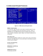
Page 39: ... about the memory chips it contains including size speed voltage row and column addresses and manufacturer CAS Latency Time When synchronous DRAM is installed the number of clock cycles of CAS latency depends on the DRAM timing Do not reset this field from the default value speci fied by the system designer Active to Precharge Delay The choices 5 6 7 DRAM RAS to CAS Delay The choices 2 3 DRAM RAS ...

Page 40: ...ove performance certain space in memory is reserved for ISA cards This memory must be mapped into the memory The choices Enabled Disabled System BIOS Cacheable Selecting Enabled allows caching of the system BIOS ROM at F0000h FFFFFh resulting in better system performance However if any program writes to this memory area a system error may result The available choices are Enabled Disabled Video BIO...

Page 41: ...On Chip VGA Setting includes On chip VGA The choices are Enabled Disabled On chip Frame Buffer Size The choices are 1MB 8 MB Boot Display The choices are Auto CRT TV EFP 40 ...

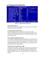
Page 42: ...le Input Output fields let you set a PIO mode 0 1 for each of the four IDE devices that the onboard IDE interface supports Modes 0 through 4 provide successively increased performance In Auto mode the system automatically determines the best mode for each device The choices are Auto Mode 0 Mode 1 Mode 2 Mode 3 Mode 4 IDE Primary Secondary Master Slave UDMA Ultra DMA 33 implementation is possible o...

Page 43: ...Modem Selecting Auto will enable the AC97 modem if it is detected onboard Init Display First This item allows you to active PCI slot or onboard display first The choices are PCI slot Onboard AGP IDE HDD Block Mode Block Mode transfers can improve the access to IDE devices Enable this item if your IDE devices support block mode transfers Power ON Function Select the different manners for powering o...

Page 44: ...T Mode Select This item allows you to select UART mode The choices Normal IrDA ASKIR SCR UR2 Duplex Mode The choices Half Full Onboard Parallel Port This item allows you to determine access On Board parallel port controller with which I O address The choices 378 IRQ7 278 IRQ5 3BC IRQ7 Disabled Parallel Port Mode Select an operating mode for the On Board parallel printer port Select Normal Compatib...

Page 45: ...is setting specifies whether your system reboots after a power failure There are three selections Off The system will remain off when power comes back after a power failure On The system will switch on when power comes back after a power failure Former Sts The system will return to the last state before the power failure when power returns ACPI Function This item allows you to Enable Disable the A...

Page 46: ...k Screen This option only writes blanks to the video buffer 3 DPMS Initial display power management signaling Video Off In Suspend This determines the manner in which the monitor is blanked The Choices Yes No Suspend Type Select the Suspend Type The Choices PwrON Suspend Stop Grant MODEM Use IRQ This determines the IRQ in which the MODEM can use The Choice 3 4 5 7 9 10 11 NA Suspend Mode When enab...

Page 47: ...DD COM LPT Port PCI PIRQ A D The events are I O events whose occurrence can prevent the system from entering a power saving mode or can awaken the system from such a mode In effect the system remains alert for anything which occurs to a device which is configured as Enabled even when the system is in a power down mode The choices Enabled Disabled 46 HDD Power Down When enabled and after the set ti...

Page 48: ...n has caused such a serious conflict that the operating system can not boot The choices Enabled Disabled Resources Controlled By The Award Plug and Play BIOS has the capacity to automatically configure all of the boot and Plug and Play compatible devices However this capability means absolutely nothing unless you are using a Plug and Play operating system such as Windows95 If you set this field to...

Page 49: ...The Choices Enabled Disabled PCI Latency Timer CLK This item controls how long each PCI device can hold the bus before another takes over INT Pin 1 4 Assignment Name the interrupt request IRQ line assigned to PCI 1 through PCI 4 on your system Activity of the selected PCI slot awakens the system The choices Auto 3 4 5 7 9 10 11 Onboard LAN 1 2 INT Assign The choices Auto 3 4 5 7 9 10 11 48 ...

Page 50: ...ge 294h to 297h for other device The choices Enabled Disabled Shutdown Temperature This item allows you to set up the CPU shutdown temperature This item is only effective under Windows 98 ACPI mode The Choices Disabled 60 0 C 140 0 F 65 0 C 149 0 F 70 0 C 158 0 F Figure 4 9 BIOS PC Health Status 49 ...

Page 51: ...ave not been locked Auto Detect PCI Clk When enabled this item will auto detect if the PCI sockets have devices and will send clock signal to PCI devices When disabled it will send the clock signal to all PCI sockets The choices Enabled Disabled Spread Spectrum Modulated This item allows you to enable disable the spread spectrum modulate to reduce EMI The choices Enabled Disabled 4 11 Frequency Vo...

Page 52: ... display that option and then press the F7 key 4 14 Set Supervisor User Password The Supervisor User Password utility sets the password The mainboard is shipped with the password disabled If you want to change the password you must first enter the current password then at the prompt enter your new password The password is case sensitive You can use up to eight alphanumeric characters Press Enter a...

Page 53: ...ng Enter will save the new setting information in the CMOS memory and continue with the booting process 4 16 Exit Without Saving Selecting this option and pressing Enter will exit the Setup Utility without record ing any new values or changing old ones 52 ...

Page 54: ...Chapter 5 Driver Installation 53 ...

Page 55: ...p 5 1 1 Place the driver installation CD ROM in your CD ROM driver Then cick My Computer on your desktop items Step 5 1 2 The menu of My Computer will display Find your drive which supports CD ROM and click that item Step 5 1 3 Select DRIVER folder Please follow the following steps to find VGA driver INF and IAA in the driver CD ROM to implement installation Note In this manual Windows 2000 is the...

Page 56: ...rs of VGA INF and IAA installation driver 5 2 Installing VGA Driver Step 5 2 1 Double click the folder of VGA The menu will display Select the folder of WIN2K_XP for Windows 2000 operating system Step 5 2 2 After the menu displays select the folder of GRAPHICS Step 5 1 4 55 ...

Page 57: ...uble click the blue sign SETUP Step 5 2 4 After a sequence of system processing you will see a static screen instructing the installation process Click Next to continue setup Step 5 2 5 If you accept License Agreement click Yes to continue 56 ...

Page 58: ...m successful completion of driver software installation and ask you to restart your computer Select Yes I want to restart my computer now and then click Finish After your computer reboots VGA driver is already setup in your computer Step 5 2 6 Step 5 2 8 Step 5 2 7 57 ...

Page 59: ...ver go back to 5 1 Go through step 5 11 to step 5 14 again and open the folder of INF to start installing INF Step 5 3 1 Open the folder of 98_ME_2K_XP Step 5 3 2 Double click the blue sign INFINST_AUT OL Step 5 3 3 Click Next to install INF 58 ...

Page 60: ...Step 5 3 4 Click Yes to continue Step 5 3 5 Click Yes Step 5 3 6 Select Yes I want to restart my computer now Then click Finish INF is installed 59 ...

Page 61: ...o back to 5 1 Go through step 5 11 to step 5 14 again and open the folder of IAA to start installing INF Step 5 4 1 After the folder of ALL_OS displays click it Step 5 4 2 Double click the blue sign IATA_CD Step 5 4 3 Click Next to install 60 ...

Page 62: ...Step 5 4 4 Click Yes Step 5 4 5 Click Next Step 5 4 6 Select Next 61 ...

Page 63: ...Click Yes Step 5 4 7 Step 5 4 8 Select Yes I want to restart my computer now then click Finish Your computer is installed with IAA 62 ...

Page 64: ...N1 9 AC_BTCLK 10 AC_SDIN2 J14 USB Connector J19 Keylock PIN No Description PIN No Description 1 VCC5 1 VCC5 2 USBP0N 2 N C 3 USBP0P 3 GND 4 USBP1N 4 Keylock 5 USBP1P 5 GND 6 GND J18 GPIO PORT Super IO PIN No Description PIN No Description 1 GP20 PIN27 2 GP24 PIN23 3 GP21 PIN26 4 GP25 PIN22 5 GP22 PIN25 6 GP26 PIN21 7 GP23 PIN24 8 GP27 PIN20 9 GND 10 GND 63 ...

Page 65: ...eyclk 2 CIRRX 2 Keydata 3 IRRX 3 N C 4 GND 4 GND 5 IRTX 5 VCC5 J 9 SMBUS Connector J 8 ATX Push Button PIN No Description PIN No Description 1 SMBDATA 1 GND 2 SMBCLK 2 Plus Signal J 11 Hardware Reset J 16 ATX Power Connector PIN No Description PIN No Description 1 GND 1 5VSBY 2 Reset 2 GND 3 PSON 64 ...

Page 66: ...J 7 Speaker J 4 IDE Active LED PIN No Description PIN No Description 1 Speaker Out 1 VCC5 2 GND 2 IDE_ACT 3 GND 4 VCC5 J 2 AUX 12 V Power Connector PIN No Description 1 GND 2 GND 3 12V 4 12V 65 ...

Page 67: ...nitored item doesn t occur before the timer reaches zero WDT performs an action such as a diagnos tic operation rebooting the computer You must enter timer values into WDT Configuration Register Write the control value to the Configuration Port and clear WDT counter read the Configuration Port WDT Configuration port F2 Default at F2 Watch Dog Timer Disabled 1 Default at disabled Enabled 2 Enabled ...

Page 68: ...on B 3 Watchdog Timer Programming Procedure B 3 1 Power On or Reset the System The initial value of WDT Control Register D3 D0 is zero 0 when power is on or the system has been reset The following table indicates the initial value of WDT 00000000b Bit Value Mean 3 0 Disable Watchdog Timer 2 1 0 0 0 0 Select 64 second Table B 3 WDT Control Register Initial Value Table B 2 WDT Control Register Bit D...

Page 69: ...to WDT configuration port Set WDT Control Register to control the WDT working mode The initial value of WDT Control Register is shown as follows Setting the WDT Control Register as AL Mov al 0h Setting initial value 0 for the WDT Control Register Follow these instructions to set the register 1 Select the time out intervals of WDT decide the values of D2 D1 D0 in F2 Example If D2 D0 0 the time out ...

Page 70: ...WDT After finishing the above settings you must output the Control Register s value to WDT Configuration Port Then WDT will start according to the above settings MOV dx F2h Setting WDT Configuration Port OUT dx al Output the Control Register Value 69 ...

Page 71: ...The Digital Infrastructure C Copyright 2003 NEXCOM International Co Ltd Version 1 0 ...

Reviews: