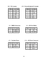
J 20 : IR Connector J 23 : External Keyboard Connector
PIN No. Description PIN No. Description
1 VCC5 1 Keyclk
2 CIRRX 2 Keydata
3 IRRX 3 N.C
4 GND 4 GND
5 IRTX 5 VCC5
J 9 : SMBUS Connector J 8 : ATX Push Button
PIN No. Description PIN No. Description
1 SMBDATA 1 GND
2 SMBCLK 2 Plus Signal
J 11 : Hardware Reset J 16 : ATX Power Connector
PIN No. Description PIN No. Description
1 GND 1 5VSBY
2 Reset # 2 GND
3 PSON #
64
Summary of Contents for PEAK 715 Series
Page 6: ...Chapter 1 General Information 5 ...
Page 12: ...Chapter 2 Jumper Setting 11 ...
Page 17: ...Chapter 3 Capability Expanding 16 ...
Page 25: ...Chapter 4 Award BIOS Setup 24 ...
Page 54: ...Chapter 5 Driver Installation 53 ...
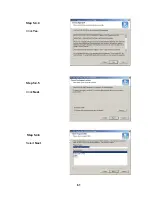
Page 62: ...Step 5 4 4 Click Yes Step 5 4 5 Click Next Step 5 4 6 Select Next 61 ...
Page 71: ...The Digital Infrastructure C Copyright 2003 NEXCOM International Co Ltd Version 1 0 ...

