background image

10

FORM NO. L-20063-AG-1216

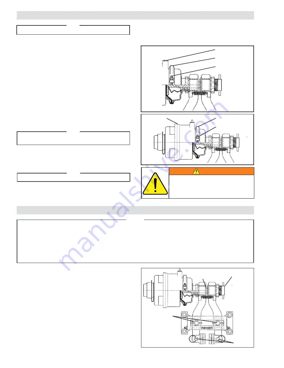
Figure  7

Actuator

Ring Clamp Bolt

Ring Clamp

Figure  8

Actuator

Ring Clamp

Ring Clamp Bolt

NOTE

Maximum operating pressure is 6.90 bar [100 psi].

Pneumatically actuated devices require clean, pressure 
regulated, and lubricated air for maximum performance and 
long life.  Your Nexen Distributor carries filters, regulators, 
and lubricators specifically designed to operate with Nexen 
clutches, brakes, and valves.

Piping diagrams are included in this manual for a variety 
of braking functions.  Refer to OPERATIONAL MODES 
(See Page 12-14).

The actuator air connections may be rotated 360

o

 by 

loosening the Ring Clamp and rotating the Actuator Head.  
If the actuator is spring engaged, first deactuate the brake 
and cage the spring.

1.  Apply hold-off air pressure to release the spring Actuator 

(See Figure 6).

 Note

Before performing step two, determine the actuator type 

and select either step 2a or 2b. 

2. 

Manual Disengagement:

  Refer to pages 16 & 17 for 

manual disengagement and re-engagement instructions.  

3.  Adjust the ring clamp as required.

 Note

Tighten Ring Clamp Bolts to 25-35 ft-lbs [34-47 Nm] torque. 

AIR CONNECTIONS–GENERAL

A Hose Assembly (Item 23) is supplied and must be 
connected to the brake with sufficient slack to allow the 
Arms (Item 2) full movement without putting stress on the 
hose or hose couplings.

Do not use rigid pipe or tubing when connecting 

directly to the brake. Care must also be taken 

to prevent an unshielded air hose from rubbing 

on metal surfaces or edges; this will cause rapid 

deterioration of the hose.

WARNING

LUBRICATION

FIGURE  9

Piston Rod

(Item 10)

Bearing

(Item 15)

Bearing

(Item 14)

Adjustment

Screw

(Item 8)

All pivot points on the BD Caliper Brake use self-lubricated 
high PV bearings.

For tension control applications where the disc is held at 
elevated temperatures for extended periods, use a light 
machine oil on Bearings (Items 14 and 15) (See Figure 9).

The sliding spherical contact between the Adjustment Screw 
(Item 8) and Piston Rod (Item 10) should be lubricated 
with a molybdenum disulfide based grease (See Figure 9).

NOTE

Nexen pneumatically actuated devices require clean, pressure regulated air for maximum performance and life.  

All seals in Nexen pneumatically operated devices are lubricated for life, and do not require additional lubrication. 

However, some customers prefer to use an air line lubricator, which injects oil into the pressurized air, forcing 

an oil mist into the air chamber. This is acceptable, but care must be taken to ensure once an air mist lubrica-

tion system is used, it is continually used over the life of the product as the oil mist may wash free the factory 

installed lubrication. 
Locate the lubricator above and within ten feet of the product, and use low viscosity oil such as SAE-10. 
Synthetic lubricants are not recommended. 

Summary of Contents for 933500

Page 1: ...1 FORM NO L 20063 AG 1216 BD Caliper Brake STANDARD AIR CHAMP PRODUCTS ...

Page 2: ...ice until the machinery into which it is to be incorporated has been declared in conformity with the applicable provisions of the Directive Read this manual carefully before installation and operation Follow Nexen s instructions and integrate this unit into your system with care This unit should be installed operated and maintained by qualified personnel ONLY Improper installation can damage your ...

Page 3: ...ion 5 Installation 6 Friction Facing Clearance Adjustment 8 Air Connections General 10 Lubrication 10 Operational Modes 11 Option Kit for 3 4 Wide Disc Installation 14 Maintenance 14 Two Port Actuator Function 15 Manual Release Procedures for Spring Actuators 16 Parts Replacement 17 Parts List 20 Warranty 21 ...

Page 4: ...ers and devices can cause injury Wear safety glasses and take the appropriate safety precautions CAUTION The temperature limits for the product are 4 5 100 degree Celsius 40 220 degree F CAUTION Surface temperature may exceed safe handling limits during operation Do not touch CAUTION This product has possible pinch points Care should be taken when interacting with this product CAUTION This product...

Page 5: ...ystem and your willingness to keep all components in proper operating condition Pay particular attention to all NOTES CAUTIONS and WARNINGS to avoid the risk of personal injury or property damage It is important to understand that these NOTES CAUTIONS and WARNINGS are not exhaustive Nexen cannot possibly know or evaluate all conceivable methods in which service may be performed or of the possible ...

Page 6: ... Ventilated Discs Table 2 Pull up Bolt Torques For Ventilated Discs S E U Q R O T G N I N E T H G I T D E D N E M M O C E R DIAMETER PART NUMBER D Q BUSHING TORQUE m m 5 0 3 n i 2 1 1 0 2 4 3 9 F S m N 5 0 4 b l t f 0 3 m m 6 5 3 n i 4 1 2 0 2 4 3 9 E m N 1 8 b l t f 0 6 m m 6 0 4 n i 6 1 3 0 2 4 3 9 E m N 1 8 b l t f 0 6 m m 7 5 4 n i 8 1 4 0 2 4 3 9 J m N 5 2 8 1 b l t f 3 3 1 m m 8 0 5 n i 0 2 ...

Page 7: ... Retainer Plate Item 6 5 Press the Pivot Pins out Item 7 6 Slide Arms Item 2 out of Main Frame Item 1 7 Position Arms and Actuator as desired 8 Reverse the above procedure to reassemble the BD Caliper Brake 9 Tighten the Cap Screws Item 24 to 7 9 Nm 5 7 ft lb torque Re Engagement NOTE On spring engaged BD Caliper Brakes apply 80 100 psi hold off air pressure and Refer to pages 16 17 for manual dis...

Page 8: ...product that is being installed Table 3 T C U D O R P R E B M U N N O I T C I R F H T D I W C S I D T C U D O R P R E B M U N N O I T C I R F H T D I W C S I D 0 0 5 3 3 9 n i 0 5 0 m m 3 1 4 9 5 3 3 9 n i 0 0 1 m m 5 2 1 0 5 3 3 9 n i 0 5 0 m m 3 1 5 9 5 3 3 9 n i 0 0 1 m m 5 2 2 0 5 3 3 9 n i 5 7 0 m m 9 1 0 0 6 3 3 9 n i 0 5 0 m m 3 1 3 0 5 3 3 9 n i 0 5 0 m m 3 1 1 0 6 3 3 9 n i 0 5 0 m m 3 1 ...

Page 9: ...ngs Item 4 and the Friction Disc See Figure 5 5 Turn the Adjustment Screw in until the spacer can just be pulled out 6 Tighten the Spanner Nut Item 12 to 13 6 20 3 Nm 10 15 ft lb torque Note Ensureproperhold offpressurehasbeenmaintained This will remove any tension on the tap bolt for easier release 7 Manual Re Engagement Refer to pages 16 17 for manual disengagement and re engagement 8 Remove hol...

Page 10: ... hose or hose couplings Do not use rigid pipe or tubing when connecting directly to the brake Care must also be taken to prevent an unshielded air hose from rubbing on metal surfaces or edges this will cause rapid deterioration of the hose WARNING LUBRICATION FIGURE 9 Piston Rod Item 10 Bearing Item 15 Bearing Item 14 Adjustment Screw Item 8 All pivot points on the BD Caliper Brake use self lubric...

Page 11: ...ged torque to the disc See Figure 11 OPERATIONAL MODES Filter Regulator Lubricator Air Supply Power Source 3 Way Valve N C Quick Exhaust Valve 3 Way Manual Valve Figure 10 optional Lubricator 3 Way Valve N C Quick Exhaust Valve Power Source Regulator Filter Air Supply 3 Way Manual Valve Connected to Spring Engaged Port Figure 11 Air Engaged Port Service Service Plug Spring Engaged Port Obsolete Th...

Page 12: ...DE 3 Way Manual Valve Air Supply Filter Regulator Lubricator Power Source Power Source Regulator Quick Exhaust Valve used as a Shuttle Valve Set at a reduced pressure for less than full rated torque Quick Exhaust Valve connected to Spring Engaged Port Figure 13 Air Engaged Port Service Service Plug Spring Engaged Port Obsolete Three Port Actuator Spring Brake Service Two Port Actuator Spring Brake...

Page 13: ... Facings Item 4 Bearings Item 14 and 15 and the machine shaft are up to twice the normal design loads Connect to Air Engaged Port Brake is cycled with Air Engaged Mode Connected to Spring Engaged Port Quick Exhaust Power source wired to Power On circuit Regulator Figure 14 Lubricator Regulator Filter Air Supply Set at minimum Hold Off pressure 75 psi 5 17 bar 3 Way Manual Valve Power Source ON 75 ...

Page 14: ... 17 for proper operation Not applicable for the 60 psi canister OPTION KIT FOR 3 4 WIDE DISC INSTALLATION INCLUDED WITH BRAKE 1 Remove Return Spring Item 17 and Shoes Item 3 by removing Shoe Pins Item 16 See Figure 15 2 Loosen the Spanner Nut Item 12 and turn the Adjustment Screw Item 8 counterclockwise until it is fully disengaged See Figure 15 3 Open the Arms Item 2 at the actuator end and repla...

Page 15: ... Mode In a power off situation with both control valves de energized the air in SPRING BRAKE chamber exhausts and the spring pushes the PUSH ROD to engage the brake Using either the spring or the air activated diaphragm with a 24 inch disc produces full brake torque of 19 000 in lbs Reducing the torque in either engagement mode is accomplished by reducing air pressure Spring engaged torque is redu...

Page 16: ...when hold off air pressure is not available DO NOT USE THE TAP BOLT TO ADJUST THE FRICTION FACING GAP Use a 9 16 inch socket wrench to turn the tap bolt counterclockwise until the brake is released Approximately 40 turns or 0 83 For easier turning of the tap bolt apply 80 100 psi hold off air pressure to remove the tension After loosening the tap bolt exhaust the air from the spring chamber DO NOT...

Page 17: ...ten the Machine Screws to 12 15 Nm 8 12 ft lb torque PARTS REPLACEMENT FRICTION FACINGS 60 PSI Actuator Only Disengagement A Cap Screw and Washer are shipped loose with the actuatorassemblyandareusedtomechanicallyrelease the spring in the event of an actuator failure or machine service when hold off air pressure is not available DO NOT USE THE CAP SCREW TO ADJUST THE FRICTION FACING GAP Use a 15 1...

Page 18: ...ssthedamagedBearings Item15 outoftheShoes Item 3 14 Press new Bearings Item 15 into Shoes Item 3 15 Slide the Arms Item 2 back into the Main Frame Item 1 Refer to Figure 19 1 Loosen the Spanner Nut Item 12 2 RemovetheAdjustmentScrew Item8 andtheSpanner Nut Item 12 from the Arm Item 2 3 Remove the Actuator Item 11 from the other Arm Item 2 4 Remove the Return Springs Item 17 and Spring Retainers It...

Page 19: ...oper seating Tighten nut to 20 25 ft lbs torque 7 Screw the actuator back into the arm and tighten the spanner nut to 10 14 ft lbs 8 Apply air pressure to the service chamber and check for air leakage Refer to pages 16 17 for Manual Disengagement and Re Engagement instructions Refer to page 8 FRICTION FACING CLEARANCE ADJUSTMENT for Air Spring Actuator re engagement and facing clearance adjustment...

Page 20: ...i t c i r F 4 8 1 4 7 w e r c S e n i h c a M 4 5 r e n i a t e R g n i r p S 2 9 1 w e r c S p a C 4 6 e t a l P r e n i a t e R n i P t o v i P 1 0 2 r e h s a W k c o L 4 7 n i P t o v i P 2 1 2 2 n w o h S t o N g u l P e p i P 8 w e r c S t n e m t s u j d A 1 2 2 n w o h S t o N r e t p a d A 9 g n i R g n i n i a t e R w e r c S t n e m t s u j d A 1 3 2 n w o h S t o N y l b m e s s A e s ...

Page 21: ...ATURE WHATSOEVER WHETHER ARISING OUT OF BREACH OF WARRANTY OR OTHER BREACH OF CONTRACT NEGLIGENCE OR OTHER TORT OR OTHERWISE EVEN IF NEXEN SHALL HAVE BEEN ADVISED OF THE POSSIBILITY OR LIKELIHOOD OF SUCH POTENTIAL LOSS OR DAMAGE For all of the purposes hereof the term consequential damages shall include lost profits penalties delay damages liquidated damages or other damages and liabilities which ...

Reviews: