background image

1

FORM NO. L-20271-E-0300

ACTUATOR

NOTE

This BD Caliper Brake is spring engaged and
hydraulically disengaged. To release the spring
pressure, remove the Vent, then lubricate and insert a
Grade 5, 3/8-16 x 9'' Threaded Rod into the back of the
Actuator; then, using a Flat Washer and Nut, tighten the
Nut to release the spring pressure (See Figure 4).  A
Manual Release Kit (Product No. 933596) containing
these items is available from Nexen.

The actuator may be mounted on either side of the
brake.

1.

Remove the Detent Pins (Item 16) to release the Shoes
(Item 3) and the Belleville Disc Springs (Item 29) (See
Figure 2).

NOTE

Two Belleville Disc Springs (Item 29) are compressed
between the Brake Arm (Item 2) and the Shoe (Item 3).
When the Shoe is removed, the Belleville Disc Springs
will fall free from the Brake Arms.

2.

Remove the Shoes (Item 3) and Belleville Disc Springs
(Item 29) (See Figure 2).

3.

Remove four Cap Screws (Item 24) (See Figure 2).

INSTALLATION

DISC

1.

Thoroughly inspect the tapered bore of the disc hub and
the tapered surface of the Q.D. bushing.  Remove any dirt,
grease, or foreign material.  Do not use lubricants for this
installation.

2.

Assemble the Q.D. bushing into the disc hub, aligning the
untapped holes in the bushing flange with the tapped
holes in the disc hub.

3.

Insert the pull-up bolts and alternately and evenly tighten
to the recommended torque (See Tables 1 and 2).

NOTE

Runout is minimized if a Dial Indicator is used as the
pull-up bolts are tightened.  Place the contact tip of the
Dial Indicator on the machined surface of the rotor to
measure runout.  Runout should be .010 - .015 In.
[2.5 - 3.8 mm] (See Figure 1).

CAUTION

If excessive tightening torque is applied, bursting
pressures are created in the hub.  There must be a gap
between the flange of the Q.D. bushing and the disc hub
to ensure a proper press fit of the Q.D. bushing onto the
shaft.

Dial

Indicator

4.

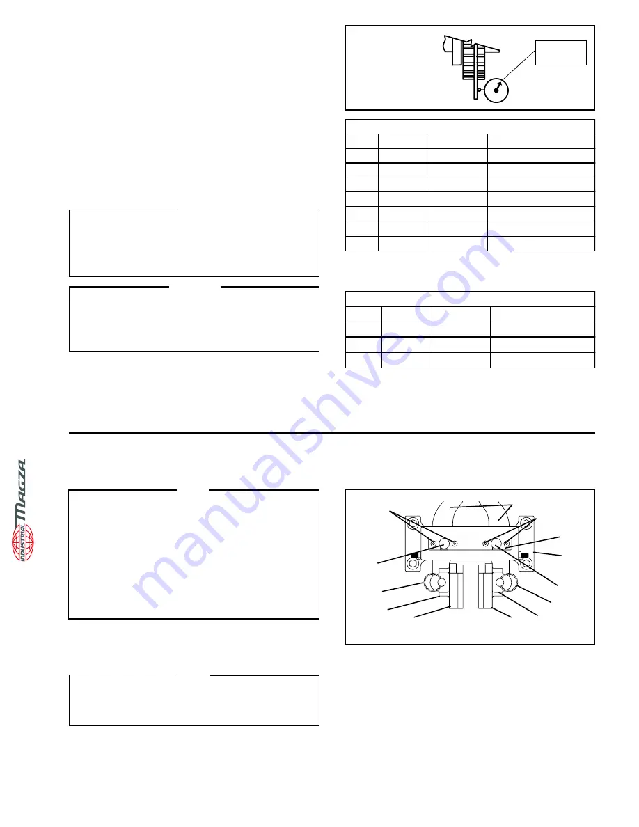
Remove Pivot Pin Retaining Plate (Item 6) (See Figure 2).

5.

Press out Pivot Pins (Item 7) (See Figure 2).

6.

Slide Brake Arms (Item 2) out of Main Frame (Item 1) (See
Figure 2).

7.

Position the Brake Arms and Actuator as desired.

8.

Slide the Brake Arms (Item 2) back into the Main Frame
(Item 1) (See Figure 2).

24

24

2

6

1

7

16

29

3

7

16

29

FIGURE  2

3

FIGURE  1

4.

To remove the Q.D. bushing, remove the pull-up bolts and
reinsert into the threaded holes.  Tighten the pull-up bolts
to push the disc hub off the Q.D. bushing.

RECOMMENDED TIGHTENING TORQUES

DIA.

PART NO.

QD BUSHING

TORQUE

12"

934201

SF

30 Ft. Lbs. [40.5 N m]

14"

934202

E

60 Ft. Lbs. [81 N m]

16"

932203

E

60 Ft. Lbs. [81 N m]

18"

934204

J

133 Ft. Lbs. [182.5 N m]

20"

934205

J

133 Ft. Lbs. [182.5 N m]

22"

934206

J

133 Ft. Lbs. [182.5 N m]

24"

934207

J

133 Ft. Lbs. [182.5 N m]

TABLE 1
PULL-UP BOLT TORQUES FOR NON-VENTILATED DISCS

RECOMMENDED TIGHTENING TORQUES

DIA.

PART NO.

QD BUSHING

TORQUE

18.25"

934200

J

135 Ft. Lbs. [182.5 N m]

21"

934300

J

135 Ft. Lbs. [182.5 N m]

24"

934400

J

135 Ft. Lbs. [182.5 N m]

TABLE 2
PULL-UP BOLT TORQUES FOR VENTILATED DISCS

®

DIST

. AUTORIZADO

MEX

 (55) 53 63 23 31

QRO (442) 1 95 72 60

MTY (81) 83 54 10 18

ventas@industrialmagza.com

Summary of Contents for AIR CHAMP BD Caliper Brake

Page 1: ... i FORM NO L 20271 E 0300 Spring Engaged Hydraulically Released BD Caliper Brake DIST AUTORIZADO MEX 55 53 63 23 31 QRO 442 1 95 72 60 MTY 81 83 54 10 18 ventas industrialmagza com ...

Page 2: ...l are based on the latest information available at the time of printing and are also subject to change without notice Technical Support 800 843 7445 651 484 5900 www nexengroup com Copyright 2000 Nexen Group Inc Nexen Group Inc 560 Oak Grove Parkway Vadnais Heights Minnesota 55127 ISO 9001 Certified DIST AUTORIZADO MEX 55 53 63 23 31 QRO 442 1 95 72 60 MTY 81 83 54 10 18 ventas industrialmagza com...

Page 3: ... this unit into your system with care This unit should be installed operated and maintained by qualified personnel ONLY Improper installation may cause injury and death Comply with all applicable codes WARNING DIST AUTORIZADO MEX 55 53 63 23 31 QRO 442 1 95 72 60 MTY 81 83 54 10 18 ventas industrialmagza com ...

Page 4: ... iv DIST AUTORIZADO MEX 55 53 63 23 31 QRO 442 1 95 72 60 MTY 81 83 54 10 18 ventas industrialmagza com ...

Page 5: ... 1 Friction Facing Clearance Adjustment 3 Maintenance 3 Lubrication 4 Parts Replacement 4 Replacement Parts 7 Parts List 7 Warranty 10 DIST AUTORIZADO MEX 55 53 63 23 31 QRO 442 1 95 72 60 MTY 81 83 54 10 18 ventas industrialmagza com ...

Page 6: ... vi NOTES DIST AUTORIZADO MEX 55 53 63 23 31 QRO 442 1 95 72 60 MTY 81 83 54 10 18 ventas industrialmagza com ...

Page 7: ...ndicator is used as the pull up bolts are tightened Place the contact tip of the Dial Indicator on the machined surface of the rotor to measure runout Runout should be 010 015 In 2 5 3 8 mm See Figure 1 CAUTION If excessive tightening torque is applied bursting pressures are created in the hub There must be a gap betweentheflangeoftheQ D bushingandthedischub to ensure a proper press fit of the Q D...

Page 8: ...d insert a Grade 5 3 8 16 x 9 Threaded Rod into the back of the Actuator then usingaFlatWasherandNut tightenthe Nut to release the spring pressure See Figure 4 A Manual Release Kit Product No 933596 containing these items is available from Nexen 2 Align the customer supplied support with the Main Frame Item 1 mounting holes NOTE The support must be capable of sustaining loads producedduringbraking...

Page 9: ...alf turns NOTE The vent in the Rear Cylinder prevents debris from entering the Belleville Spring stack and relieves any pressure built up by the reciprocating action of the Piston Flat Washer Nut Actuator FIGURE 5 Grade 5 3 8 16 x 9 Threaded Rod Adjustment Screw Item 8 Spanner Nut Item 12 Friction Disc FIGURE 6 Vent Item 17 28 27 MAINTENANCE 1 Adhere to the following bolt torques See Table 3 DANGE...

Page 10: ...Springs Item 29 are compressed between the Brake Arm Item 2 and the Shoe Item 3 When the Shoe is removed the Belleville Disc Springs will fall free from the Brake Arms 3 Remove Detent Pins Item 16 to release Friction Facings Item 4 Shoes Item 3 and Belleville Disc Springs Item 29 from Brake Arms Item 2 See Figure 8 4 Remove Friction Facings Item 4 from the Shoes Item 3 by removing the old Machine ...

Page 11: ...JUSTMENT HIGH PV SLEEVE BEARINGS NOTE This BD Caliper Brake is spring engaged and hydraulically disengaged To release the spring pressure remove the Vent then lubricate and insert a Grade 5 3 8 16 x 9 Threaded Rod into the back of the Actuator then usingaFlatWasherandNut tightenthe Nut to release the spring pressure See Figure 4 A Manual Release Kit Product No 933596 containing these items is avai...

Page 12: ...re 11 7 Separate the Cylinder Head Item 12 from the Front Cylinder Item 2 and remove the old Wiper Seal Item 4 See Figure 11 8 Press a new Wiper Seal Item 4 into the Cylinder Head Item 12 9 Remove the Small Washer Item 15 and old Rod Seal Item 6 from the Front Cylinder Item 2 See Figure 11 NOTE TheRodSeal Item6 iscoatedwithaspecialcompound Avoid excessive handling of the Rod Seal 10 Press a new Ro...

Page 13: ...ills of materials and instruction manuals When ordering replacement parts specify model designation item number part description and quantity Purchase replacement parts through your local Nexen Distributor PARTS LIST MANUAL RELEASE KIT Product No 933596 ITEM DESCRIPTION QTY 1 Grade 5 3 8 16 x 9 Threaded Rod 1 2 3 8 16 Nut 1 3 3 8 Flat Washer 1 FIGURE 12 1 2 3 NOTE 1 500Lbs 6 672N offorceisrequired...

Page 14: ... 2 28 Hex Nut 2 291 2 Belleville Disc Spring 4 301 Sleeve Bearing 2 ITEM DESCRIPTION QTY 1 Main Frame 1 2 Brake Arm 2 3 Shoe 2 41 2 Friction Facing 2 5 Spring Clip 2 6 Pivot Pin Retaining Plate 1 7 Pivot Pin Arm 2 8 Adjustment Screw 1 9 Adjustment Screw Retaining Ring 1 12 Spanner Nut 1 FIGURE 13 2 2 9 12 26 8 5 17 1 27 28 30 15 3 4 18 16 14 7 6 24 5 29 MAIN FRAME 1 Denotes Repair Kit items Repair...

Page 15: ... 15 10 12 7 4 6 16 8 FIGURE 14 ACTUATOR ITEM DESCRIPTION QTY 1 Piston 1 2 Front Cylinder 1 3 Rear Cylinder 1 41 Wiper Seal 1 51 Piston Seal 1 61 Rod Seal 1 71 Sleeve Bearing 1 8 Belleville Disc Spring 36 9 Spherical Shaft End 1 9 18 17 1 Denotes repair kit items Repair Kit No 933597 Repair Kit includes two Alignment Pins Not Shown s DIST AUTORIZADO MEX 55 53 63 23 31 QRO 442 1 95 72 60 MTY 81 83 5...

Page 16: ...lied with the warranty claim procedures set out below in WarrantyClaimProcedures ExclusiveRemedy The sole and exclusive remedy for a breach of this warrant shall be at Nexen s sole election repair or replacement with new serviceably used or reconditioned Product or issuance of a credit in the amount of the current Nexen discounted price for the Product Limitation of Damages In no event shall Nexen...

Reviews: