5
FORM NO. L-21699-B-1120
PRODUCT DESCRIPTION
The Rod Lock has been developed for locking and holding on the shaft of an air cylinder or guide rod. These spring engaged,
air released units are designed to hold in a safe position by default. Brakes are intended for static holding applications
and Emergency Stop situations.
The proper installation and maintenance of these rod locks must be observed to prevent damage to unit or improper use of unit.
Engaged State:
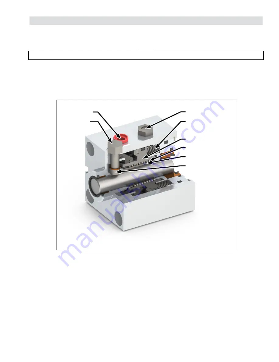
In the engaged state, several compression springs push on the piston causing the clamping collar to lock
onto the rod. If air pressure is lost the unit will default to the brake engaged state.
Disengaged State:
When air pressure is applied, the piston will push back against the springs, releasing the clamping
collar from the rod. Manual release units are also equipped with a cam operated manual release
feature to mechanically disengage the rod lock
A series of equally spaced compression springs provide the rod lock actuating force. Dozens
of ball bearings separate a split, tapered collar and piston. The piston travels up the ramp on
the collar under spring force and causes the split collar to constrict on the rod. Air pressure
applied to the opposite side of the piston compress the springs to release the grip on the rod.
Select models have a manual release feature to disengage the rod lock without air pressure.
The mechanism is cam operated, turned with a wrench and is a “default-to-lock” function. As
long as a force is applied to the wrench the rod lock is disengaged. With no force applied the
rod lock “defaults” to the engaged position.
NOTE
PISTON
COMPRESSION
SPRINGS
BREATHER VENT
AIR INLET
BALL BEARINGS
SPLIT COLLAR
MANUAL
RELEASE
HEX NUT
MANUAL
RELEASE CAM
Figure 2 Principle of Operation


