9
FORM NO. L-21699-B-1120
OPTIONAL OPERATING MODE SENSOR(S)
Nexen’s Magnetic Proximity Sensors are available to
gather operational data from the Rod Lock. The Safety
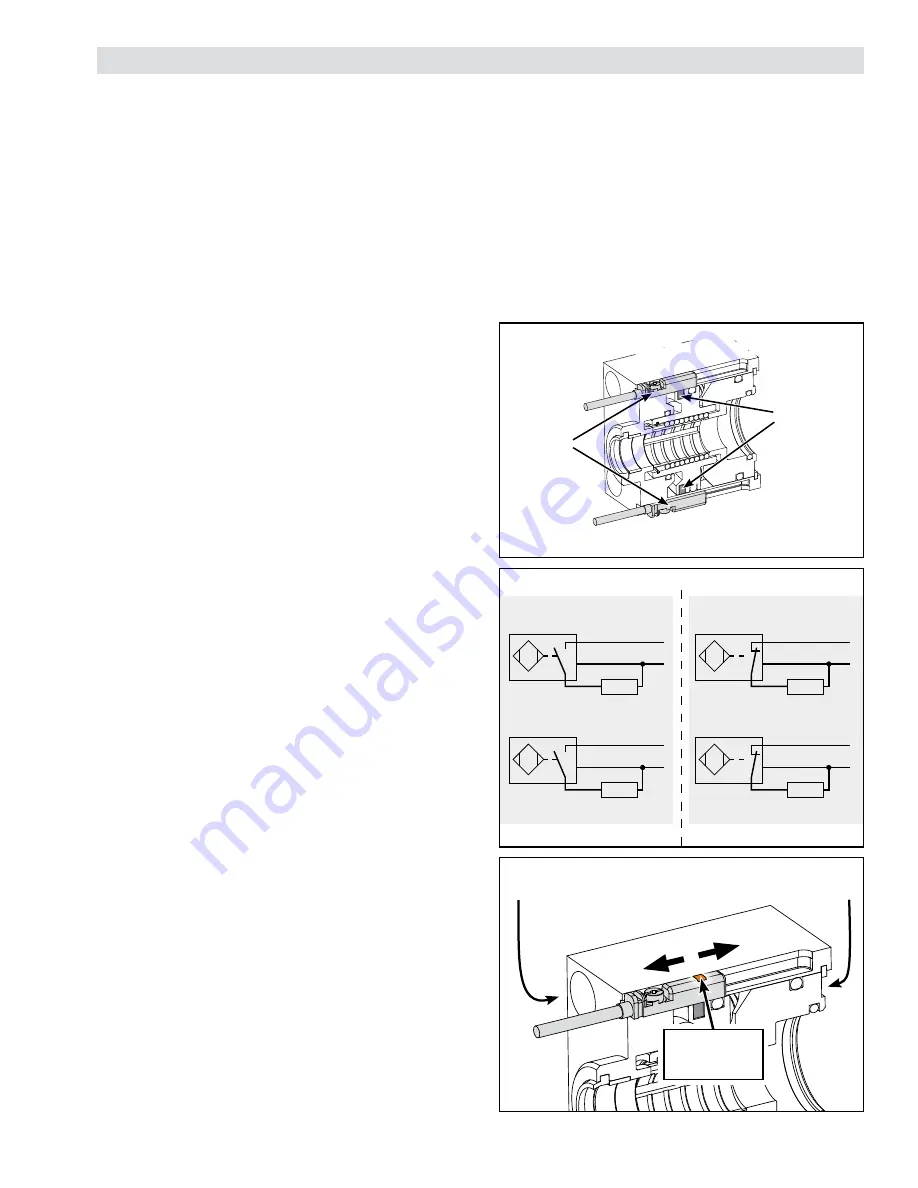
Rated RLSSB can be equipped with one or two T-slots
for sensor mounting.
These sensors may be used by system manufacturers
to gain higher safety category ratings per ISO 13849-1.
Rating of the safety function is the responsibility of the
system manufacturer.
Each Proximity sensor can be set up to sense one of the
following functions of the Rod Lock:
Disengagement Sensor Definition:
Sensor is activated when the rated air pressure is applied
and the piston moves to a disengaged position.
Engagement Sensor Definition:
Sensor is activated when the piston moves out of the
disengaged position into a position in which the clamp
collar constricts on the rod.
SENSOR WIRING
Nexen’s Magnetic Proximity Sensor is available in two
modes, see
Table 2
. System manufacturer is responsible
for selecting appropriate sensor type for specified safety
application.
PNP Mode (Sourcing)
Normally Open (N.O.) or Normally Closed (N.C.) PNP
type Sourcing Output available, see
Figure 5
. Typically
matched with a PLC Sinking Input.
NPN Mode (Sinking)
Normally Open (N.O.) or Normally Closed (N.C.) NPN type
Sinking Output available, see
Figure 5
. Typically matched
with a PLC Sourcing Input.
SENSOR INSTALLATION AND SETUP
Note: Validate sensor functionality in application, including
possible temperature range.
The Rod Lock can be equipped with one or two magnetic
proximity sensors. If two sensors are used, they can be
configured to detect redundant or individual engaged and
/ or disengaged states. If sensors are setup for redundant
detection, the sensor states should always match. If
sensors are setup for individual, opposing detection, the
sensor states should always be opposite. To ensure proper
operation, compare the expected state to the measured
state. Once installed on the rod, Nexen recommends
checking the positioning of the sensor for proper switching
location.
Wire magnetic sensor and insert cable clip into t-slot per
the instructions included with the sensor(s). Provide power
to sensor, and complete the following:
Sensing Disengagement Position:
1. With rod lock on rod, supply air pressure to the rod
lock so it is disengaged.
2. Install sensor as shown in
Figure 6
. Start with sensor
positioned closest to the
back
of the rod lock, past the
sensing target. Slide the sensor towards the
front
end
of the rod lock until LED is lit. Once the LED is lit, move
sensor a small amount further into sensing target.
3. Use a standard flat-head screwdriver or 1.5mm allen
wrench to turn the screw and fix the sensor in the t-slot.
4. Cycle air pressure to ensure the LED is lit only when
release air pressure is supplied to the rod lock.
BK
BU
-
BN
+
LOAD
NPN Mode (Sinking)
NPN Mode (Sinking)
PNP Mode (Sourcing)
BK
BU
BN
LOAD
PNP Mode (Sourcing)
BK
BU
BN
BK
BU
BN
LOAD
LOAD
0 VDC
10-30 VDC
-
+
0 VDC
10-30 VDC
-
0 VDC
+
10-30 VDC
-
0 VDC
+
10-30 VDC
Figure 5
Sensor Wiring
Figure 4
Locking
Mode
Sensor(s)
Sensing
Magnet
Note: Safety Rated Units may have
one or two sensor slots.
Sensing Engagement Position:
1. With rod lock on rod, remove air pressure to the rod
lock so it is engaged.
2. Install sensor as shown in
Figure 6
. Start with sensor
positioned closest to the
front
of the rod lock, before
the sensing target is reached. Slide the sensor
towards the
back
end of the rod lock until LED is
lit. Once the LED is lit, move sensor a small amount
further into sensing target.
3. Use a standard flat-head screwdriver or 1.5mm allen
wrench to turn the screw and fix the sensor in the t-slot.
4. Cycle air pressure to ensure the LED is lit only when
air pressure is removed from the brake.
Figure 66
(Engagement)
(Disengagement)
Sensor Adjustment Direction
Back
End of
Rod Lock
Front
End of
Rod Lock
LED Light
LED Light
on Sensor
on Sensor
Note: Ferrous Materials in Close Proximity
may interfere with sensor function.
Normally Open:
Normally Closed:


