50
10
0
20
0
30
0
C
4 00
5 00
600
700
F
50
150
250
350
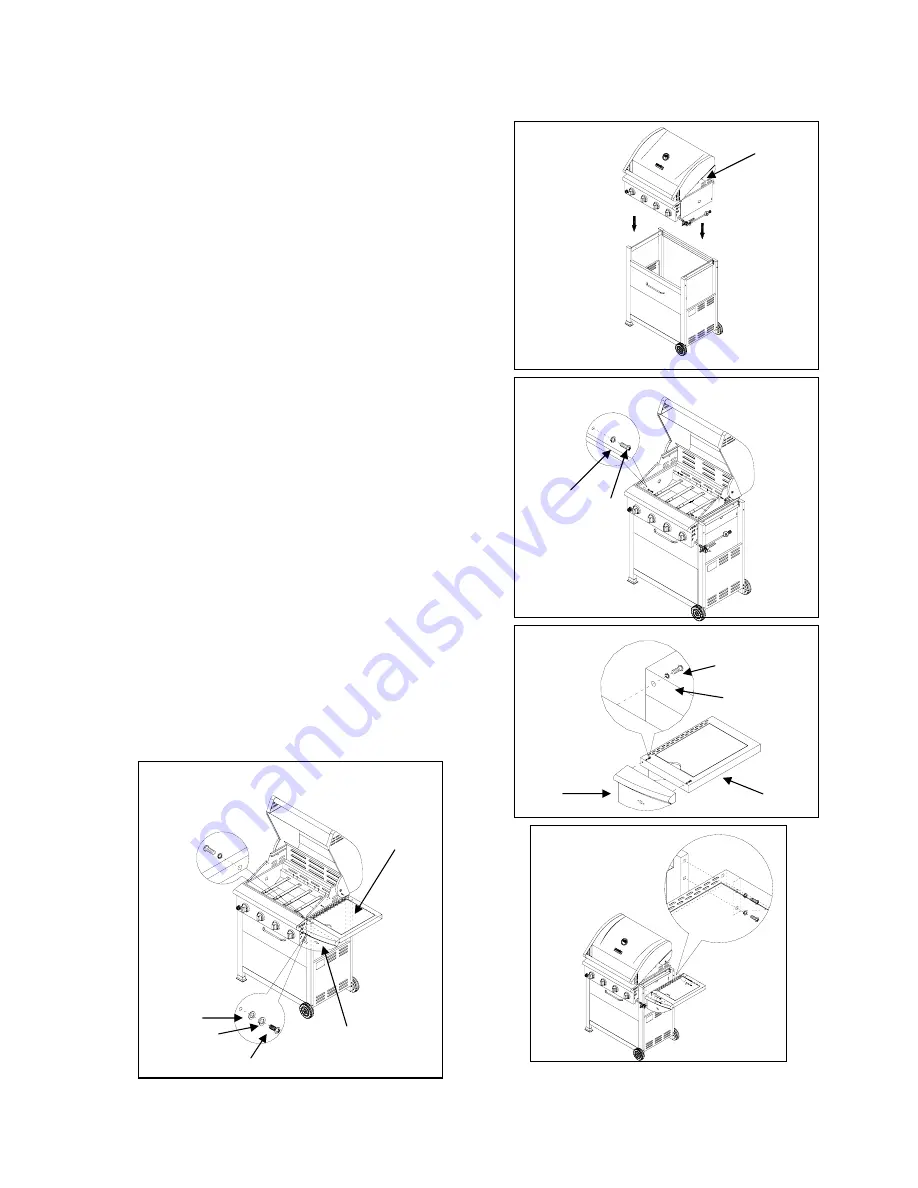
8. Firebox Assembly
NOTE: Obtain the aid of an assistant to lift the firebox. Be
sure the hose and regulator hang outside the cart when
placing Firebox. See Fig. 14.
a). With the aid of an assistant, lift the Firebox and carefully
carefully place it onto the grill cart see Fig.14.
b) Raise firebox lid and from inside the Firebox use 4 CC
Round Head Screws and 4 DD Lock Washers to attach the
sides of Firebox to Cart Brace, Left (F) and Cart Brace, Right
(J). Raise Firebox slightly to align holes for inserting and
tightening screws. See Fig. 15.
9. Side Burner Shelf Assembly
a). Use 2 AA Round Head Screws and 2 BB Lock Washers
to attach Side burner front panel (V) to Side Burner (U). See
Fig. 16.
b) Align the holes on Side Burner (U) with the holes on the
side of Front Right Cart Leg (G) and Rear Right Cart Leg
(H), and attach with 4 AA Round Head Screws and 4 BB
Lock Washers. See Fig. 17. Note: Do not fully tighten the
four screws at this point
c) Align the holes on Side Burner (U) with the holes on the
side of firebox, and attach from inside of firebox using 2 CC
Round Head Screws and 2 DD Lock Washers. See Fig. 18
d) Connect Side Burner front panel (V) to Main control Panel
with 1 AA Round Head Screw (AA) and 1 BB Lock Washer
and 1 GG Flat Washer. See Fig. 18.
A
DD
CC
Fig.14
Fig.15
V
BB
AA
U
Fig.16
12
Fig. 18
GG
BB
AA
U
V
Fig. 17


