background image

1.Safety Precautions and Warnings

To prevent personal injury or damage to vehicles and/or the scan 

tool, read this instruction manual first and observe the following 

safety precautions at a minimum whenever working on a vehicle:

•    

•    Wear safety eye protection that meets ANSI standards.

•    Keep clothing, hair, hands, tools, test equipment, etc. away from 

     all moving or hot engine parts.

•    Operate the vehicle in a well ventilated work area: Exhaust gases 

     are poisonous.

•    Put blocks in front of the drive wheels and never leave the vehicle 

      unattended while running tests.

•    Use extreme caution when working around the ignition coil, 

     distributor cap, ignition wires and spark plugs. These components 

     create hazardous voltages when the engine is running.

•    Put the transmission in PARK (for automatic transmission) or

     NEUTRAL (for manual transmission) and make sure the parking 

     brake is engaged.

•    Keep a fire extinguisher suitable for gasoline/chemical/ electrical 

     fires nearby.

•    Don't connect or disconnect any test equipment while the ignition 

     is on or the engine is running.

•    Keep the scan tool dry, clean, free from oil/water or grease. Use a 

     mild detergent on a clean cloth to clean the outside of the scan tool, 

     when necessary.

Always perform automotive testing in a safe environment.

1

Summary of Contents for NX301

Page 1: ...N 301 X R NEXPEAK OBDII Scanner NX301 ...

Page 2: ......

Page 3: ...Start Diagnostics 4 1 1 4 2 Read Codes 4 3 Erase Codes 4 4 Live Data 4 4 1 View Data 4 4 2 Record Data 4 4 3 Playback Data 4 5 View Freeze Frame Data 4 6 Retrieve I M Readiness Status 4 7 Oxygen O2 Sensor Monitor Test 4 8 On Board Monitor Test 4 9 Component Test 4 10 View Vehicle Information 4 11 LED Interpretation 5 Print Diagnostic Report 6 Update The Scan Tool 7 Appendix 7 1 Appendix 1 PID List...

Page 4: ...aten anzeigen 4 5 2 Daten aufzeichnen 4 5 3 Wiedergabe Daten 4 6 Aussicht Gefrorener Rahmen Daten 4 7 Abrufen I M Bereitschaft Status 4 8 Sauerstoff O2 Sensor Monitor Prüfung 4 9 Am Bordmonitor Prüfung 4 10 Komponenten Prüfung 4 11 Ansicht Fahrzeuginformationen 4 12 LED Deutung 5 Drucken Diagnose bericht 6 Aktualisieren Das Scan Werkzeug 8 Dienst Verfahren 7 Blinddarm 7 1 Anhang 1 PID Liste Verzei...

Page 5: ...attended while running tests Use extreme caution when working around the ignition coil distributor cap ignition wires and spark plugs These components create hazardous voltages when the engine is running Put the transmission in PARK for automatic transmission or NEUTRAL for manual transmission and make sure the parking brake is engaged Keep a fire extinguisher suitable for gasoline chemical electr...

Page 6: ...e Engine Soon The system will also store important information about the detected malfunction so the a technician can accurately find and fix the problem The system will give the following information 1 Whether the Malfuncaion Indicator Lght MIL is commanded on or off 2 Which if any Diagnostic Trouble Codes DTCs are sored 3 Readiness Monitor status 2 2 Diagnostic Trouble Codes DTCs OBD II Diagnost...

Page 7: ...tools interface with the vehicle s on board computer The DLC is usually located 12 inches from the center of the instrument panel dash under or around the driver s side for most vehicles If the Data Link Connector is not located under the dashboard a label should be there indicating an alternate location For some Asian and European vehicles the DLC is located behind the ashtray which must be remov...

Page 8: ...for engine misfire and monitoring fuel demands Non Continuous Monitors Unlike the continuous monitors many emissions and engine system components require the vehicle to be operated under specific conditions before the monitor is ready These monitors are termed non continuous monitors and are listed below 1 EGR System 2 O2 Sensors 3 Catalyst 4 Evaporative System 5 O2 Sensor Heater 6 Secondary air 7...

Page 9: ...finitions Powertrain Control Module PCM OBD II terminology for the on board computer that controls engine and drivetrain Malfunction Indicator Light MIL Malfunction Indicator Light Service Engine Soon Check Engine is a term used for the light on the instrument panel It is to alert the driver and or the repair technician that there is a problem with one or more of vehicle s systems and may cause em...

Page 10: ...n an emissions related fault occurs OBD II system not only sets a code but also records a snapshot of the vehicle operating parameter to help in identifying the proble This set of values is referred to as Freeze Frane Data and may include engine parameters such as engine PRM vehicle speed air flow engine load fuel pressure fuel trim vale engine coolants ignition timing advance or colosed loop stat...

Page 11: ...le 3 USB cable Used to upgrade the scan tool and to print retrieve X 3 4 Tool Description 1 OBD IT CONNECTOR Connects the scan tool to the vehicle s Data Link Connector DLC 2 LCD DISPLAY Displays menus and test results 3 GREEN LED Indicates that engine systems are running 4 YELLOW LED Indicates there is a possible problem A pending DTC is present and or some of the vehicle s emission monitors have...

Page 12: ...language setup hot key when pressed 3 5 DTC Lookup The DTC lookup function is used to search for definitions of DTCs stored in built in DTC library 1 From the main menu the UP DOWN scroll button to select DTC Lookup and press ENTER button 2 6 Main Menu Diagnostics Review Data Print Data System Setup Tool Information DTC Lookup The number x x in the top right indicates total number of items under t...

Page 13: ...wer OW Sete automatic power off limits 5 Beeo Set Turns beep on off 6 Tool Self Test Checks if the LCD display and keyboard are working normally Settings of the unit will remain at their default until changes to the existing settings are made To enter the setup menu mode From the keyboard Press the ESC button to ener System Setup Menu Follow the instrucions to make adjustments and settings as desc...

Page 14: ...Tool Self test 2 Use the UP DOWN scroll button to select the desired langusge and press ENTER button to save your selection and return to previous menu 1 6 Language English Français Español Deutsch Pусский Dutch Contrast Adjustment 1 From the System Setup menu use UP DOWN scroll button to select Contrast and press ENTER button From the Main Menu Use the UP DOWN scroll button to select System Setup...

Page 15: ...ER button to save your settings and return to previous menu Unit of Measurement Metric is the default measurement system 1 From the System Setup menu use UP DOWN scroll button to select Unit of Measure and press ENTER button 3 6 System Setup Unit of Measure Language Contrast Auto Power off Beep Set Tool Self test 2 From the Unit of Measure menu use the UP DOWN scroll buton to select the desired un...

Page 16: ...uto Power off Tool Self test 2 From the Beep Set menu use the UP DOWM scroll button to select Beep ON or Beep OFF to turn on off the beep 3 Press the ENTER button to save your selection and return to previous menu Tool Self test The Tool Self test function checks if the display an keyboard are working properly A Display test The Display Test funcion checks if the LCD display is working normally 1 ...

Page 17: ... start test Look for missing spots in the solid black characters 4 When completed Press ESC button to return B Keybiard Test The Keyboard Test funcion verifies if the keys are funcioning properly 1 Use the UP DOWN scroll button to seleck keyboard Test from the Tool Self test menu and then press the ENTER button 2 Press any key to start the test When you press a key the key name should be observed ...

Page 18: ... emissions control information VECI Label which is located under the hood of engine or by the radiator of most vehicles If the vehicle is OBD II compliant the label will designate OBD II Certified Additionally Government regulations mandate that all OBD II compliant vehicles must have a common 16 pins Data Link Connector DLC VEHICLE EMISSION CONTROL INFORMATION motor co inc ENGINE FAMILY EFN2 8YBT...

Page 19: ...matically boots up 4 1 2 Connecting to Personal Computer with USB Cable The code reader also receives power through the USB port when it is connected to a PC for updating software and transferring saved files To connect to PC 1 Insert the small end of the USB cable to the USB port at the right side of the code reader and the large end to a computer 2 Press the power switch of the code reader to po...

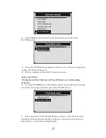
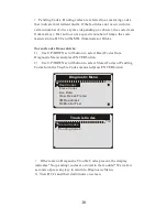
Page 20: ...oll button to select Read Codes from Diagnostic Menu and press ENTER button 2 Use UP DOWN scroll button to select Stored Codes or Pending Codes form the Trouble Codes menu and press ENTER button 1 11 Diagnostic Menu Read Codes Erase Codes Live Data View Freeze Frame I M Readiness O2 Monitor Test 1 2 Trouble Codes Srored Codes Pending Codes If there are no Diagnostic Trouble Codes present the displ...

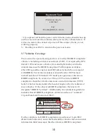
Page 21: ...4 3 Erase Codes CAUTION 1 To clear codes make sure that the ignition key is switched to ON with the engine off 2 Erase codes does not fix the problem that caused the fault DTCs should only be erased after correcting the condition s that caused them by a technician To clear codes 1 Use UP DOWN scroll buttons to select Erase Codes from Diagnostics Menu and press ENTER button 2 11 Diagnostic Menu Rea...

Page 22: ...codes are cleared successfully an Erase Done confirmation message shows on the display Erase Codes Erase Done Press any key to con If the codes are not cleared then an Erase Failure Turn Key on with Engine off message appears Erase Codes Erase Failure Turn Key on with Engine Off Press any key to con 4 Press any button to return to Diagnostic Menu 18 ...

Page 23: ...ata from Diagnostic Menu and press ENTER button 3 11 Diagnostic Menu Read Codes Erase Codes View Freeze Frame I M Readiness O2 Monitor Test Live Data 2 Wait a few seconds while the scan tool validates the PID MAP Live Data Reading PID 01 Please Wait 3 Use UP DOWN scroll button to select View Data from Live Data menu and press ENTER button 1 3 Live Data View Data Record Data Playback Data 19 ...

Page 24: ... CL FUEL SYS2 CL LOAD_PCT 0 0 ECT F 417 The number x to the right of the screen indicates sequence of highlighted item If you want to view full name of the highlighted PID press Help button If the icon appears when a PID is highlighted it indicates graphic information is available Press ENTER to view graph RPM min 975 1725 925 6 Press ESC button to return to previous menu You are allowed to pick u...

Page 25: ...ER button to start recording B DTC Trigger automatically records PID data when a fault that causes a DTC to set is detected by vehicle CAUTON DO NOT try to drive and operate the scan tool at the same time Always have another person operate the scan tool while driving 2 3 Live Data View Data Playback Data Record Data The scan tool keeps recording PID data until user presses ESC button selected memo...

Page 26: ...g 2 Use UP DOWN button to select the memory location marked with an asterisk icon 1 6 Review Data Location 1 Location 2 Location 3 Location 4 Location 5 Location 6 If there is no recording in selected location a message Not Supported or Stored No Data displays on the screen For data stored in temporary cache you do not have to select memory location 3 Use UP DOWN button to view recorded PIDs of ea...

Page 27: ...o select View Freeze Frame from Diagnostic Menu and press ENTER button 4 11 Diagnostic Menu Read Codes Erase Codes Live Data I M Readiness O2 Monitor Test View Freeze Frame 2 Wait a few seconds while the scan tool validates the PID MAP View Freeze Frame Reading PID 01 Please Wait 3 If retrieved in formation covers more than open screen then a down arrow will appear Use DOWN scroll button as necess...

Page 28: ...le models may support two types of I M Readiness tests A DTCs Cleared indicates status of the monitors since the DTCs are erased B This Drive Cycle indicates status of monitors since the beginning of the current drive cycle An I M Readiness Status result of NO does not necessarily indicate that the vehicle being tested will fail the state I M inspection For some states one or more such monitors ma...

Page 29: ...e status of the MIL light ON or OFF and the following monitors Misfire monitor Misfire monitor Fuel System Mon Fuel System Monitor Comp Component Comprehensive Components Monitor EGR EGR System Monitor Oxygen Sens Mon 02 Sensors Monitor Catalyst Mon Catalyst Monitor EVAP System Mon Evaporative System Monitor Oxygen Sen htr Oxygen Sensor Heater Monitor Sec Air System Secondary Air Monitor Htd Catal...

Page 30: ...retrieval and viewing of O2 sensor monitor test results for the most recently performed tests from the vehicle s on board computer The O2 Monitor Test function is not supported by vehicles which communicate using a controller area network CAN For O2 Monitor Test results of CAN equipped vehicles see chapter On Board Mon Test 1 Use UP DOWN scroll button to select O2 Monitor Test from Diagnostic Menu...

Page 31: ...en 2 2 O2 Monitor Test 02 Mon B1S1 02 Mon B1S2 O2 Monitor Test The selected mode is not supported Press any key to con 4 View test results of selected O2 sensor 1 3 O2 Mon B1S2 Rich to lean sensor V MEAS 6 9939 V MIN 3 9352 V MAX 4 8097 V STS Fall 5 Use UP DOWN scroll button to view more screens of data if an UP or DOWN icon displays 6 Press ESC button to return to the previous menus 27 ...

Page 32: ...st for CAN equipped vehicles retrieves and displays test results for emission related power train components and systems that are and are not continuously monitored Test and components IDs arc determined by the vehicle manufacturer 1 Use UP DOWN scroll button to select On Board Mon Test from Diagnostic Menu and press ENTER button 7 11 Diagnostic Menu On Board Mon Test Component Test Vehicle Info M...

Page 33: ...message will be displaye on the screen On Board Mon Test The selected mode is not supported Press any key to con 1 4 On Board Mon Test Catalyst Mon B1 02 Heater Mon B1S1 02 Heater Mon B1S2 Heated Catalyst B1 4 Use UP DOWN scroll button to select the desired monitor from On Board Mon Test menu and press ENTER button 5 View test data on screen Catalyst Mon B1 Lean to rich sensor V MEAS 6 0540 V MIN ...

Page 34: ... on board computer to start the test Different vehicle manufacturers might have different criteria and methods for stopping the test once it has been started Before starting the Component Test refer to the vehicle service manual for instructions to stop the test 1 Use UP DOWN scroll button to select Component Test from Diagnostic Menu and press ENTER button 8 11 Diagnostic Menu On Board Mon Test V...

Page 35: ...lected mode is not supported Pree any key to con 4 Wait a few seconds or press any key to return to Diagnostic Menu 4 10 Viewing Vehicle Information The Vehicle Info function enables retrieval of Vehicle Identification No VIN Calibration ID s Calibration Verification No CVN and In use Performance Tracking on 2000 and newer vehicles that support Mode 9 1 Use UP DOWN scroll button to select Vehicle ...

Page 36: ...TCs are found 2 YELLOW LED shows the tool finds a possible problem Pending DTCs exist or and some of the vehicle s emission monitors have not run their diagnostic testing 3 RED LED indicates there are some problems in one or more of the vehicle s systems In this case the MIL lamp on the instrument panel is on A Repair the vehicle yourself If you are going to perform the repairs yourself proceed by...

Page 37: ... scanner to computer with the USB cable supplied 3 Run the UPLINK exe in your PC 4 Use the UP DOWN scroll button to select Print Data from Main Menu in the scan tool and press the OK button 5 Use the UP DOWN scroll button to select the desired item to print from Print Data menu To print all retrieved data use the UP DOWN scroll button to select Print All Data from Print Data menu 6 Press the OK bu...

Page 38: ...ion 7 Restart the scan tool to finish the whole update Please ignore the Microsoft Modem drivers install failure if you are not using windows XP system Device Driver Installation Wizard Completing the Device Driver Installation Wizard Some drivers were successfully installed on this computer Some could not be installed See the Status column for more details if a device came with your software you ...

Page 39: ...ne Coolant Temperature Engine Coolant Temperature Short Term Fuel Trim Bank1 Short Term Fuel Trim Bank3 Long Term Fuel Trim Bank1 Long Term Fuel Trim Bank3 Short Term Fuel Trim Bank2 Short Term Fuel Trim Bank4 Long Term Fuel Trim Bank2 Long Term Fuel Trim Bank4 Fuel Rail Pressure gauge Fuel Rail Pressure gauge Intake Manifold Absolut Pressure Intake Manifold Absolut Pressure Engine RPM Vehicle Spe...

Page 40: ...2 Sensor Output Voltage B1S3 Short Term Fuel Trim B1S3 O2 Sensor Output Voltage B1S4 Short Term Fuel Trim B1S4 O2 Sensor Output Voltage B2S2 Short Term Fuel Trim B2S2 O2 Sensor Output Valtage B2S3 Short Term Fuel Trim B2S3 O2 Sensor Output Voltage B2S4 Short Term Fuel Trim B2S4 O2 Sensor Output Voltage B2S1 Short Term Fuel Trim B2S1 O2 Sensor Output Voltage B1S2 Short Term Fuel Trim B1S2 O2 Sensor...

Page 41: ...l Pres Relative To Manifold Vacuum Fuel Rail Pressure Fuel Rail Pressure Equivalence Ratio wide range O2S B1S1 O2 Sensor Voltage wide range O2S B1S1 Equivalence Ratio wide range O2S B1S2 O2 Sensor Voltage wide range O2S B1S2 Equivalence Ratio wide range O2S B1S3 O2 Sensor Voltage wide range O2S B1S3 Equivalence Ratio wide range O2S B1S4 O2 Sensor Voltage wide range O2S B1S4 Equivalence Ratio wide ...

Page 42: ...2S B3S2 O2 Sensor Voltage wide range O2S B3S2 Equivalence Ratio wide range O2S B4S1 O2 Sensor Voltage wide range O2S B4S1 Equivalence Ratio wide range O2S B4S2 O2 Sensor Voltage wide range O2S B4S2 Commanded EGR EGR Error Commanded Evaporative Purge Fuel Level Input Number of Warm ips Since DTC Cleared Distance Since DTC Cleared Distance Since DTC Cleared Evap System Vapor Pressure Evap System Vpo...

Page 43: ...ange O2S B2S1 Equivalence Ratio wide range O2S B1S2 O2 Sensor Current wide range O2S B1S2 Equivalence Ratio wide range O2S B2S1 O2 Sensor Current wide range O2S B2S1 Equivalence Ratio wide range O2S B2S2 O2 Sensor Current wide range O2S B2S2 Equivalence Ratio wide range O2S B3S1 O2 Sensor Current wide range O2S B3S1 Equivalence Ratio wide range O2S B3S2 O2 Sensor Current wide range O2S B3S2 Equiva...

Page 44: ...PI CATCONDI OBD Monitoring Conditions Encountered Encountered Counts Ignition Counter Catalyst Monitor Completion Counts Bank 1 Catalyst Monitor Conditions Encountered Const Bank OBD Monitoring Conditions Encountered Counts displays ESC for the number of times that the vehicel has been operated in the specified OBD monitoring conditions general denominator Ignition Counter displays the count of ES...

Page 45: ...n have been encountered numerator O2 Sensor Monitor Completion Encountered Counts Bank 1 displays ESC number of times that the vehicle has been operated in the specified oxygen sensor monitoring gonditions denominator O2 Sensor Monitor Completion Counts Bank 2 displays ESC number of times that all conditions necessary to detect an oxygen sensor bank 2 malfunction have been encountere numerator O2 ...

Page 46: ...en operated in the specified AIR system monitoring conditions denominator EVAP Monitor Completion Condition Counts dispalys ESC number of time that all conditions necssary to detect a 0 O2 EVAP system leak malfunction have been encountered numerator EVAP Monitor Conditions Encountered Counts displays ESC number of times that the vehicle has been operated in the specified EVAP system leak malfuncit...

Page 47: ...Blöcke vor die Antriebsräder und lassen Sie das Fahrzeug während der Tests niemals unbeaufsichtigt Bei Arbeiten an Zündspule Zündverteilerkappe Zünd Drähten und Zündkerzen ist äußerste Vorsicht geboten Diese Komponenten erzeugen gefährliche Spannungen wenn der Motor läuft Stellen Sie das Getriebe in PARK für Automatikgetriebe oder NEUTRAL für Schaltgetriebe und stellen Sie sicher dass die Feststel...

Page 48: ... Außerdem mit integriertem Speicherchip ermöglicht dem Benutzer gespeicherte Diagnosedaten über PC auszudrucken und ein lebenslanges kostenloses Update sorgt dafür dass Sie sich in Zukunft keine Sorgen mehr um Ihr Auto machen müssen 2 2 Spezifikation 1 Anzeige Hintergrundbeleuchtung 128 x 64 Pixel Display mit Kontrast Einstellen 2 Betriebs Temperatur 0 bis 60 32 bis 140 F 3 Lagertemperatur 20 bis ...

Page 49: ...Fahrzeugs 2 LCD BILDSCHIRM Zeigt Menüs und Testergebnisse an 3 GRÜNE LED Zeigt an dass Motorsysteme laufen 4 GELBE LED Zeigt an dass ein Problem vorliegt Ein anstehend DTC ist vorhanden und oder einige der Emissionsüberwachung Geräte des Fahrzeugs haben ihre Diagnoseprüfung nicht durchgeführt 5 ROTE LED Zeigt an dass ein Problem in einem oder mehreren Fahrzeugsystemen vorliegt Die rote LED zeigt a...

Page 50: ...rd wird der aktuelle Bildschirm für weitere Daten durchsucht Es wird auch als Sprache Setup Hotkey beim Drücken verwendet 3 2 Sprache einrichten Benutzen Sie die AUFWÄRTS ABWÄRTS und LEFT RIGHT Scrolltasten um System Setup im Hauptmenü auszuwählen und drücken Sie OK Der Bildschirm zeigt die folgende Oberfläche an 5 6 Main Menu Diagnostics DTC Lookup Review Data Print Data Tool information System S...

Page 51: ...t Wenn das Fahrzeug OBD II konform ist wird das Etikett OBD II zertifiziert bezeichnen Zusätzlich Regierungsvorschriften schreiben vor dass alle OBD II konformen Fahrzeuge einen gemeinsamen 16 poligen Data Link Connector DLC haben müss Drücken Sie die ENTER Taste um das Hauptmenü aufzurufen Benutzen Sie die AUFWÄRTS ABWÄRTS Scrolltasten zur Auswahl von Diagnostics aus dem Menü en VEHICLE EMISSION ...

Page 52: ...vicehandbuch des Fahrzeugs für den Standort oder kontaktieren Sie uns online 4 2 Starten Diagnose Wenn mehr als ein Fahrzeugsteuermodul vom Diagnosegerät erkannt wird werden Sie aufgefordert das Modul auszuwählen in dem die Daten abgerufen werden können Am häufigsten werden das Motorsteuermodul PCM und das Getriebesteuergerät TCM ausgewählt VORSICHT Schließen Sie keine Testgeräte an oder trennen S...

Page 53: ...iederholen Sie den Vorgang ab Schritt 5 Wenn die Meldung LINKING ERROR nicht verschwindet kann es Probleme geben dass das Diagnose Tool mit dem Fahrzeug kommuniziert Wenden Sie sich an Ihren lokalen Händler oder an den Kundendienst des Herstellers 7 Sie werden aufgefordert zuvor gespeicherte Daten zu löschen Überprüfen Sie zuvor gespeicherte Daten gründlich bevor Sie sie löschen Wenn keine Daten i...

Page 54: ...eisen auf Probleme hin die das Steuermodul während des aktuellen oder letzten Fahrzyklus festgestellt hat gelten aber noch nicht als ernst Ausstehende Codes schalten die Fehlfunktionsanzeige MIL nicht ein Wenn der Fehler nicht innerhalb einer bestimmten Anzahl von Aufwärmzyklen auftritt wird der Code aus dem Speicher gelöscht 1 Verwenden Sie die AUFWÄRTS ABWÄRTS Tasten um Codes aus dem Diagnosemen...

Page 55: ...stellerspezifisch werden in der oberen rechten Ecke des Displays angezeigt Wenn mehr als ein DTC gefunden wird verwenden Sie die AUFWÄRTS ABWÄRTS Taste falls erforderlich bis alle Codes angezeigt wurden Wenn die abgerufenen Fehlercodes herstellerspezifische oder erweiterte Codes enthalten wird die Meldung Herstellerspezifische Codes gefunden Drücken Sie eine beliebige Taste zur Auswahl der Fahrzeu...

Page 56: ...Löschen Sie die Codes nicht bevor das System vollständig von einem Techniker überprüft wurde 1 Verwenden Sie die AUFWÄRTS ABWÄRTS Tasten um Codes aus dem Diagnosemenü auszuwählen und drücken Sie die ENTER Taste 2 11 Diagnosemenü Lese Codes Live Daten Anzeig Freeze Frame I M Staus Lamdasonde Prüfung Losche Codes 1 28 Fahrzeughersteller FORRE GM CHRYSLER BENZ BMW VW AUDI AUFWÄRTS ABWÄRTS Taste falls...

Page 57: ...e ein wenn die Engine ausgeschaltet ist Erscheint 4 Drücken Sie eine beliebige Taste um zum Diagnosemenü zurückzukehren 4 5 Lebensdaten 4 5 1 Daten anzeigen Die Funktion Daten anzeigen ermöglicht die Anzeige von Echtzeit oder Echtzeit PID Daten des Computermoduls des Fahrzeugs S 1 Um Live Daten anzuzeigen verwenden Sie die AUFWÄRTS ABWÄRTS Taste um Live Data aus dem Diagnosemenü auszuwählen und dr...

Page 58: ...len und drücken Sie die Taste EINGABE 5 Zeigen Sie Live PIDs auf dem Bildschirm an Verwenden Sie die AUFWÄRTS ABWÄRTS Taste für weitere PIDs wenn auf dem Bildschirm ein AUF oder AB Pfeil erscheint Die Zahl x rechts vom Bildschirm zeigt die Reihenfolge des markierten Elements an Wenn Sie den vollständigen Namen der hervorgehobenen PID anzeigen möchten drücken Sie die Taste Hilfe 1 84 Live Daten DTC...

Page 59: ...aten FID der Fahrzeugmodule um intermittierende Fahrzeugprobleme zu diagnostizieren Eine Aufzeichnung enthält 5 Bilder von Live Daten vor dem Trigger Ereignis und mehrere Frames nach dem Trigger Ereignis Es gibt zwei Triggermodi die zum Aufzeichnen von Daten verwendet werden A Manueller Trigger ermöglicht dem Benutzer die ENTER Taste zu drücken um die Aufnahme zu starten B DTC Trigger zeichnet aut...

Page 60: ...n Sie die RNTER Taste 3 3 Live Daten Datenanzeige Datenauzeichnung Datenwiedergabe Sie können auch aufgenommene Daten sofort nach der Aufnahme wiedergeben 2 Wählen Sie mit den Tasten AUFWÄRTS ABWÄRTS den Speicherplatz der mit einem Sternchen gekennzeichnet ist Wenn an dem ausgewählten Ort keine Aufzeichnung stattfindet wird eine Meldung Nicht unterstützt oder Keine Daten gespeichert auf dem Bildsc...

Page 61: ...ositive Frames zeigen Daten an die nach dem Triggerereignis aufgezeichnet wurden 4 6 Aussicht Gefrorener Rahmen Daten 1 Um Gefrorener Rahmen Daten anzuzeigen verwenden Sie die AUFWÄRTS ABWÄRTS Taste um Freeze Frame anzeigen im Diagnosemenü auszuwählen und drücken Sie die ENTER Taste 4 11 Diagnosemenü Lese Codes Losche Codes Live Daten I M Staus Lamdasonde Prüfung Anzeig Freeze Frame 2 Warten Sie e...

Page 62: ...ebige Taste drücken um zum vorherigen Bildschirm zurückzukehren 4 7 Abrufen I M Bereitschaft Status Die I M Readiness Funktion wird verwendet um den Betrieb des Emissionssystems an OBD2 konformen Fahrzeugen zu überprüfen Es ist eine ausgezeichnete Funktion zu verwenden bevor ein Fahrzeug in Übereinstimmung mit einem staatlichen Emissionsprogramm inspiziert wird A DTCs Cleared zeigt den Status der ...

Page 63: ...e Frame Lamdasonde Prüfung I M Staus 2 Wenn das Fahrzeug beide Arten von Tests unterstützt werden beide Typen zur Auswahl auf dem Bildschirm angezeigt 1 2 I M Status Seit L schung DTCS ö Dieser fahrt 3 Benutzen Sie die AUFWÄRTS ABWÄRTS Taste um den Status der MIL Leuchte ON oder OFF und der folgenden Monitore anzuzeigen Fehlzündung Monitor Fehlzündung Monitor Kraftstoffsystem Mon Kraftstoffsystem ...

Page 64: ...n Tests vom Bordcomputer des Fahrzeugs 1 Verwenden Sie die AUFWÄRTS ABWÄRTS Taste um den O2 Monitor Test im Diagnosemenü auszuwählen und drücken Sie die ENTER Taste 6 11 Diagnosemenü Lese Codes Losche Codes Live Daten Anzeig Freeze Frame I M Staus Lamdasonde Prüfung Lamdasonde Prüfung L e s e P I D 0 6 B i t t e w a r t e n 2 Warten Sie ein paar Sekunden während das Diagnose Tool den PID MAP valid...

Page 65: ...rstützt Jeder Taste fortsetze 4 Zeigen Sie die Testergebnisse des ausgewählten O2 Sensors an O2 Mon B1S2 Sensor fett zu mager V MEAS 0 0000 V MIN 0 0000 V MAX 0 0000 V STS Pass 1 3 5 Verwenden Sie die AUFWÄRTS ABWÄRTS Taste um weitere Bildschirme mit Daten anzuzeigen wenn ein AUFWÄRTS oder ABWÄRTS Symbol angezeigt wird 6 Drücken Sie die ESC Taste um zu den vorherigen Menüs zurückzukehren 61 ...

Page 66: ...tete Fahrzeuge liefert Testergebnisse für emissionsbezogene Antriebsstrangkomponenten und systeme die ständig überwacht werden und nicht überwacht werden und zeigt diese an Test und Komponenten IDs werden vom Fahrzeughersteller ermittelt 1 Verwenden Sie die AUFWÄRTS ABWÄRTS Tasten um On Board Mon auszuwählen Testen Sie im Diagnosemenü und drücken Sie die ENTER Taste 7 11 Diagnosemenü Monitor prüfu...

Page 67: ...Modus nicht unterstützt wird eine Hinweismeldung auf dem Bildschirm angezeigt 1 4 Monitor prüfung Catalyst Mon B1 Heizung Mon B1S1 Beheizter Katalysator B1 Heizung Mon B1S2 4 Verwenden Sie die AUFWÄRTS ABWÄRTS Tasten um den gewünschten Monitor von On Board Mon auszuwählen Testen Sie das Menü und drücken Sie die ENTER Taste 5 Zeigen Sie Testdaten auf dem Bildschirm an 02 Heizung Mon B1 S1 SOD TEST ...

Page 68: ...se Tool selbst führt den Lecktest nicht durch sondern befiehlt dem Bordcomputer des Fahrzeugs den Test zu starten Verschiedene Fahrzeughersteller haben möglicherweise unterschiedliche Kriterien und Methoden um den Test nach dem Start zu stoppen Bevor Sie den Komponententest starten lesen Sie im Wartungshandbuch des Fahrzeugs nach wie Sie den Test stoppen können 1 Verwenden Sie die AUFWÄRTS ABWÄRTS...

Page 69: ...n das zu testende Fahrzeug den EVAP Lecktest nicht unterstützt wird eine Hinweismeldung auf dem Bildschirm angezeigt Evap Leak Pr fung ü Der gewählte Modus wirdnicht unterstützt Jeder Taste fortsetze 4 Warten Sie einige Sekunden oder drücken Sie eine beliebige Taste um zum Diagnosemenü zurückzukehren 4 11 Ansicht Fahrzeuginformationen Die Funktion Fahrzeug info ermöglicht den Abruf von Fahrzeugi d...

Page 70: ...eit üfung Fahrzug Info 2 Warten Sie ein paar Sekunden während das Diagnose Tool die Fahrzeug informationen liest Fahrzug Info L e s e P I D 0 6 B i t t e w a r t e n 3 Anzeigen der abgerufenen Fahrzeug informationen auf dem Bildschirm 9 11 Fahrzuug Info VIN WBAVC57548NK78049 CID1 7602216 CID2 7625429 CIN1 F72C8FB0 CIN2 A4649AC0 4 Drücken Sie die ESC Taste um zum vorherigen Menü zurückzukehren 66 ...

Page 71: ... Frage ob das Fahrzeug für einen Emissionstest bereit ist von den Emissionsvorschriften und Gesetzen Ihrer Region ab HINWEIS Ermitteln Sie anhand des Code Abrufverfahrens den Status jedes Monitors und leiten Sie diese Informationen an einen Fachmann weiter um festzustellen ob Ihr Fahrzeug für einen Emissionstest bereit ist basierend auf Ihren Testergebnissen 3 ROTE LED Zeigt an dass ein Problem mi...

Page 72: ...s tunVerwenden Sie kein Windows XP System 2 Schließen Sie den Scanner mit dem mitgelieferten USB Kabel an den Computer an 3 Führen Sie die UPLINK exe auf Ihrem PC aus 4 Wählen Sie mit der AUF AB Taste die Option Daten drucken aus dem Hauptmenü Menü im Scan Tool und drücken Sie die OK Taste 5 Wählen Sie mit der AUF AB Taste die gewünschte Option aus Drucken aus dem Menü Daten drucken Um alle abgeru...

Page 73: ...y to Back Finish Cancel Bitte ignorieren Sie den Installationsfehler der Microsoft Modem Treiber wenn Sie kein Windows XP System verwenden 69 2 Führen Sie uplink exe auf Ihrem Computer aus Mac OS ist nicht kompatibel 3 Halten Sie eine beliebige Taste gedrückt bis das USB Kabel mit dem Computer verbunden ist und lassen Sie sie los wenn das Diagnose Tool die Meldung Aktualisierungsmodus anzeigt 4 Ke...

Page 74: ...ne Coolant Temperature Engine Coolant Temperature Short Term Fuel Trim Bank1 Short Term Fuel Trim Bank3 Long Term Fuel Trim Bank1 Long Term Fuel Trim Bank3 Short Term Fuel Trim Bank2 Short Term Fuel Trim Bank4 Long Term Fuel Trim Bank2 Long Term Fuel Trim Bank4 Fuel Rail Pressure gauge Fuel Rail Pressure gauge Intake Manifold Absolut Pressure Intake Manifold Absolut Pressure Engine RPM Vehicle Spe...

Page 75: ...2 Sensor Output Voltage B1S3 Short Term Fuel Trim B1S3 O2 Sensor Output Voltage B1S4 Short Term Fuel Trim B1S4 O2 Sensor Output Voltage B2S2 Short Term Fuel Trim B2S2 O2 Sensor Output Valtage B2S3 Short Term Fuel Trim B2S3 O2 Sensor Output Voltage B2S4 Short Term Fuel Trim B2S4 O2 Sensor Output Voltage B2S1 Short Term Fuel Trim B2S1 O2 Sensor Output Voltage B1S2 Short Term Fuel Trim B1S2 O2 Sensor...

Page 76: ...l Pres Relative To Manifold Vacuum Fuel Rail Pressure Fuel Rail Pressure Equivalence Ratio wide range O2S B1S1 O2 Sensor Voltage wide range O2S B1S1 Equivalence Ratio wide range O2S B1S2 O2 Sensor Voltage wide range O2S B1S2 Equivalence Ratio wide range O2S B1S3 O2 Sensor Voltage wide range O2S B1S3 Equivalence Ratio wide range O2S B1S4 O2 Sensor Voltage wide range O2S B1S4 Equivalence Ratio wide ...

Page 77: ...2S B3S2 O2 Sensor Voltage wide range O2S B3S2 Equivalence Ratio wide range O2S B4S1 O2 Sensor Voltage wide range O2S B4S1 Equivalence Ratio wide range O2S B4S2 O2 Sensor Voltage wide range O2S B4S2 Commanded EGR EGR Error Commanded Evaporative Purge Fuel Level Input Number of Warm ips Since DTC Cleared Distance Since DTC Cleared Distance Since DTC Cleared Evap System Vapor Pressure Evap System Vpo...

Page 78: ...ange O2S B2S1 Equivalence Ratio wide range O2S B1S2 O2 Sensor Current wide range O2S B1S2 Equivalence Ratio wide range O2S B2S1 O2 Sensor Current wide range O2S B2S1 Equivalence Ratio wide range O2S B2S2 O2 Sensor Current wide range O2S B2S2 Equivalence Ratio wide range O2S B3S1 O2 Sensor Current wide range O2S B3S1 Equivalence Ratio wide range O2S B3S2 O2 Sensor Current wide range O2S B3S2 Equiva...

Page 79: ...TR CATCIMPI OBD Monitoring Conditions Encountered Encountered Counts Ignition Counter Catalyst Monitor Completion Counts Bank 1 OBD Monitoring Conditions Encountered Counts displays ESC for the number of times that the vehicel has been operated in the specified OBD monitoring conditions general denominator Ignition Counter displays the count of ESC number of times that the engine has been started ...

Page 80: ...n have been encountered numerator O2 Sensor Monitor Completion Encountered Counts Bank 1 displays ESC number of times that the vehicle has been operated in the specified oxygen sensor monitoring gonditions denominator O2 Sensor Monitor Completion Counts Bank 2 displays ESC number of times that all conditions necessary to detect an oxygen sensor bank 2 malfunction have been encountere numerator O2 ...

Page 81: ... system monitoring conditions denominator EVAP Monitor Completion Condition Counts dispalys ESC number of time that all conditions necssary to detect a 0 O2 EVAP system leak malfunction have been encountered numerator EVAP Monitor Conditions Encountered Counts displays ESC number of times that the vehicle has been operated in the specified EVAP system leak malfunciton monitoring conditions denomin...

Page 82: ......

Page 83: ...NEXPEAK Techonology Co Ltd www nexpeaktech com support nexpeaktech com www facebook com nexpeaktech www twitter com nexpeak_tech ...

Reviews: