background image

6

DR 4305 NexStar Installation and Operation


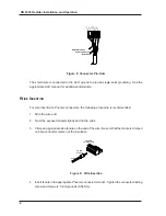
Data twisted pair

Power and Ground 

twisted pair

SHIELD

GROUND

DATA–

DATA+

+28 VDC

Figure 8: Connector Pin-Outs

The shield wire is connected to the ACU ground to provide single-point grounding.  See the
appropriate ACU manual for additional information.

W

IRE

 I

NSERTION

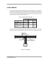
For wire insertion to Phoenix connectors, the following procedure is recommended:

1. Strip the wire end.

2. Twist the exposed strands tightly and tin the ends.

3. Crimp an appropriate size ferrule on the end of the wire.  Be sure that the ferrule is crimped

on bare conductor metal, not the insulation.

CRIMP

SLEEVE

WIRE

PHOENIX

CONNECTOR

Figure 9:  Wire Insertion

4. Insert ferrule in the appropriate Phoenix connector terminal.  Tighten the connector binding

screw and torque to 5 inch-pounds (0.56Nm).

Summary of Contents for AD 4305

Page 1: ...AD 4305 RS 485 MULTIPLEXER Installation and Operation 5452 Betsy Ross Drive Santa Clara CA 95054 1184 408 727 5170 FAX 408 727 6707 P N 66109923001 Rev A ...

Page 2: ... 1996 Westinghouse Security Electronics All rights reserved DigiReader QuadraKey DuraKey NexKey and NexStar aretrademarksofWestinghouseSecurityElectronics Printed in the United States of America ...

Page 3: ... V accessories used as integral to WSE systems have been approved by WSE e g coaxial cables batteries etc and VI the equipment has been installed the installation supervised or installation tested by an authorized WSE dealer WSE shall at its option either repair or replace free of charge the equipment found upon WSE s inspection to be so defective WSE MAKES NO OTHER WARRANTY AND ALL IMPLIED WARRAN...

Page 4: ...instructions herein may cause harmful interference to radio communications If this equipment does cause interference to radio or television reception consult the dealer or an experienced radio television technician for correction The user may find helpful the following booklet prepared by the Federal Communications Commission How to Identify and Resolve Radio TV Interference Problems This booklet ...

Page 5: ...ave installed this type of device have another person check the connections before turning on the power The warranty is void if you damage any component because of an error in wiring a connection Follow these basic procedures and precautions to avoid damage to the components local codes and practices may also apply and must be complied with ...

Page 6: ... 9 List of Figures Figure Description Page 1 S Net Layout using a NexStar 1 2 NexStar 2 3 Cover Label 3 4 NexStarBase and Mounting Holes 3 5 NexStar Printed Circuit Assembly 4 6 Transmit LEDs 5 7 TerminationJumper 5 8 ConnectorPin Outs 6 9 Wire Insertion 6 10 Drop Wiring 7 11 S NetTermination 8 12 BranchIsolation 10 13 Alternate Branch Isolation 10 List of Tables Table Description Page 1 Specifica...

Page 7: ... data it receives to the other four ports Bus arbitration is done on a first come first served basis During periods of no activity the NexStar automatically places all 5 ports into the receive mode to wait for the next message The NexStar provides a link between a WSE access control unit such as the NexSentry or SE 818SC and multiple S Net runs A single S Net run may be a maximum of 4000 feet 1200...

Page 8: ...Table 1 Specifications Input Voltage 15 to 28 VDC Opera ting Current 50mA Pass Thru Current 2A Operating Humidity 0 to 90 non condensing Operating Temperature 4 F to 50 F 20 C to 50 C Size 8 in X 4 5 in X 1 5 in 20 cm X 11 cm X 3 5 cm Weight 13 oz 400 g PHYSICAL DESCRIPTION The NexStar consists of a single printed circuit assembly PCA in a two part housing Male Phoenix connectors on the PCA are ac...

Page 9: ...5 SHIELD COMMON DATA DATA 28 VDC SHIELD COMMON DATA DATA 28 VDC SHIELD COMMON DATA DATA 28 VDC SHIELD COMMON DATA DATA 28 VDC SHIELD COMMON DATA DATA 28 VDC Figure 3 Cover Label BASE The base of the housing has four through holes for mounting the NexStar to a wall or other surface Four standoffs are affixed to support the PCA 3 2 in 8 1 cm 7 29 in 18 5 cm MOUNTING HOLE 4 PLACES STANDOFF 4 PLACES F...

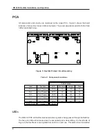
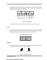
Page 10: ...ion Label Function LED Connector Jumper Fuse TX 1 Port 1 Transmit CR18 J5 JP5 F5 TX 2 Port 2 Transmit CR17 J4 JP4 F4 TX 3 Port 3 Transmit CR16 J3 JP3 F3 TX 4 Port 4 Transmit CR15 J2 JP2 F2 TX 5 Port 5 Transmit CR14 J1 JP1 F1 COM ACTIVE Active CR19 LEDS The COM ACTIVE LED will be illuminated when any data is being passed through the NexStar The five port LEDs will illuminate when the associated por...

Page 11: ...h speed network communications may cause all LEDs to appear illuminated FUSES Each of the five ports on the NexStar is individually fused Fuses for the ports are located at positions F1 through F5 on the PCA These fuses are 2 amp normal blow Approved suppliers for replacement fuses and the vendor s part numbers are shown in Table 3 Table 3 Approved Fuse Vendors Vendor Part Number Littlefuse 273002...

Page 12: ...ation WIRE INSERTION For wire insertion to Phoenix connectors the following procedure is recommended 1 Strip the wire end 2 Twist the exposed strands tightly and tin the ends 3 Crimp an appropriate size ferrule on the end of the wire Be sure that the ferrule is crimped on bare conductor metal not the insulation CRIMP SLEEVE WIRE PHOENIX CONNECTOR Figure 9 Wire Insertion 4 Insert ferrule in the app...

Page 13: ...le Table 4 Recommended S Net Cable Type Description Gauge S Net Length 500 Feet Data and Power Belden 9552 Belden 1069 2 Pair 18 AWG 16 AWG S Net Length 500 Feet Data Only Belden 9841 1 Pair 24 AWG S Net Length 500 Feet Power Only Belden 9341 Belden 9342 Belden 9343 2 Conductor 18 AWG 16 AWG 14 AWG S Net cable should be installed as a single cable splices should be soldered or secured with crimp l...

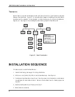
Page 14: ...igure 7 for installing the termination jumpers for NexStar ports Figure 11 S Net Termination INSTALLATION SEQUENCE The basic steps to install the NexStar are 1 Install S Net wiring See page 7 for wiring information 2 With cover on to protect the PCA mount te NexStar base See Figure 4 3 Terminate S Net branches at each end See the above for information on termination requirements for each S Net bra...

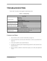
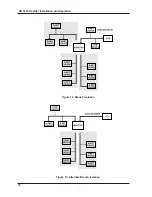
Page 15: ...eady except on one port Data A and data B wiring may be reversed Check wiring on port with unlit LED Excessive data errors Check wiring shield connections for ground loops Check termination resistors and jumpers COMMUNICATIONS ERRORS 1 Keep port with the ACU connected to the NexStar see Figure 12 2 If the ACU branch does not include other S Net devices connect a second branch see Figure 13 3 Verif...

Page 16: ...10 DR 4305 NexStar Installation and Operation Figure 12 Branch Isolation Figure 13 Alternate Branch Isolation ...

Reviews: