- Installation instructions for supplementary outriggers -
Via Mediterraneo, 6 - 42022 - Boretto - Reggio Emilia - Italy
Tel. +39 - 0522-96 30 08 - Fax +39 - 0522-96 30 39
info@maxiliftcrane.com
- 11 -
7 - FIXING SYSTEM BY CLAMP COLLAR
FOR SERIES “ML” – “0” – “1” – “2” – “3”
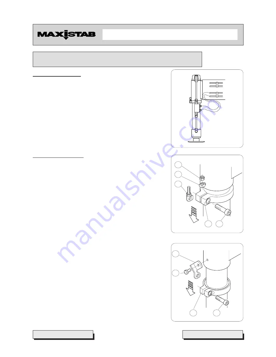
7.1 Supply conditions
The stabilizer is supplied with outrigger cylinders already fixed in the position
shown in Pict. 11, and locked in a way which does not require any
further operation to be carried out by the installer, in case such position
is suitable for the type of mounting.
IMPORTANT
Should cylinder position need to be different, the installer
must conform scrupulously to the below described instructions
7.2 Fixing instructions
In case you want to change cylinder position in comparison to the
one it has been supplied in, first of all you have to unscrew the lock
nut (
1
) (Pict. 12) of the fall and slewing preventing system; therefore
it is necessary to pay attention to the accidental and uncontrolled
descent of the cylinder itself, which may cause limbs crushing.
Concerning cylinders of series
“0”/”ML”
, please refer to Pict. 12a.
-
Unscrew the locking screw (
2
) of the clamp (
3
), and pull it out,
consequently releasing also the coupling (
4
).
-
In order to open wide the collar, you have to screw the screw
(
2
) from the threaded side (Pict. 13), placing a shim or the
coupling itself in the split.
-
Let the collar slide up to the desired position, and lock it
unscrewing the screw previously fitted in.
-
Put the screw (
2
) back into its original position, slipping it into
the hole of the adjustable coupling (
4
) inserted in the split.
Let the cylinder slide upwards (Pict. 14), until the collar leans against
the cylinder sleeve, so that the threaded shank of the coupling (
4
)
slips into the eyelet (
5
), and can be locked by tightening the lock nut
(
1
).
Pict. 11
Pict. 12
Pict. 12a
1
5
4
3
2
4
1
3
2


