010
www.ruggedaq.com
1
DATALOGGER
NI2400
NI2400
011
www.ruggedaq.com
1
DATALOGGER
NI2400
NI2400
Example 1 (2 wires sensors)
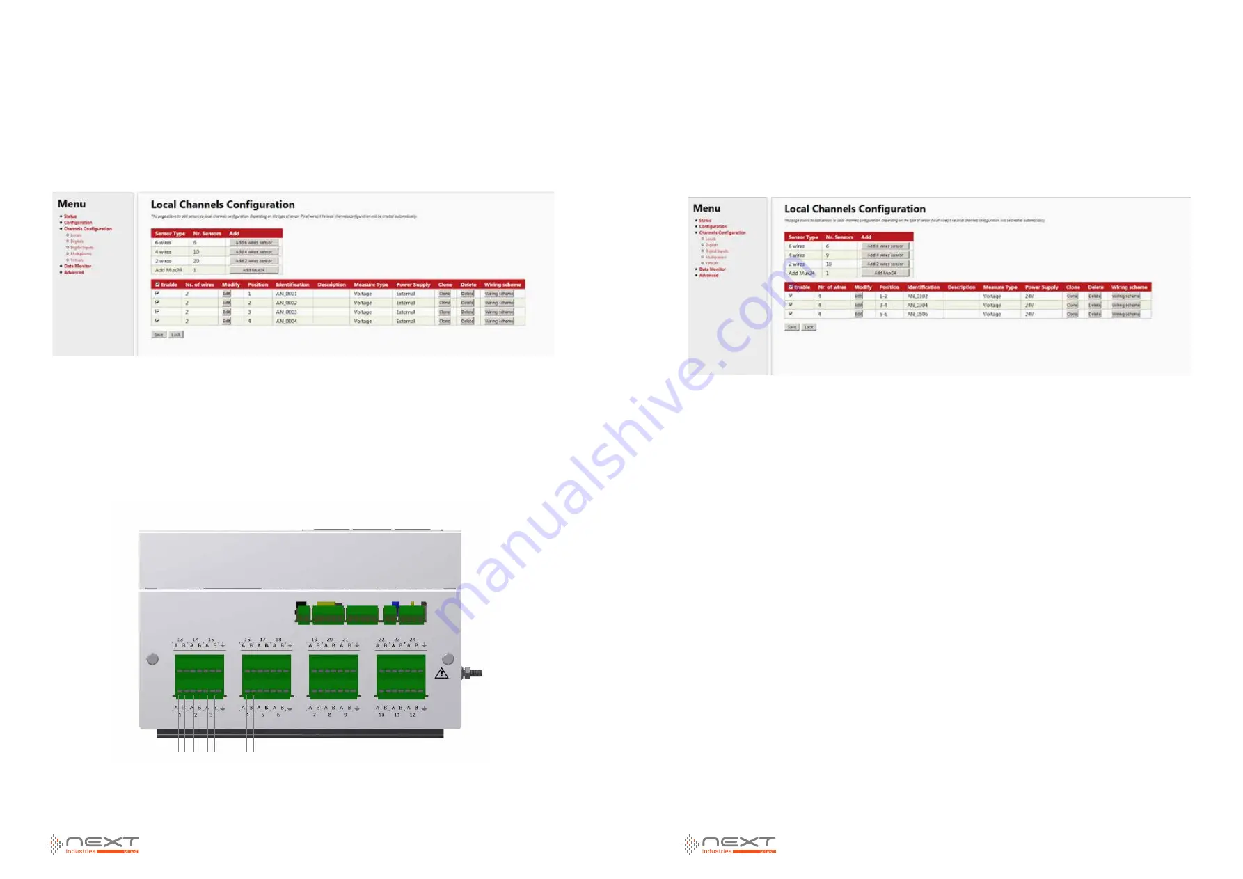
User connects 4 sensors, all of them are 2 wires:
First of all we configure the datalogger to read this sensors, as shown in Figure 4.
Figure 4
Now we can proceed with physical configuration.
SENSOR1 will be connected to channel 1, A and B terminals.
SENSOR2 will be connected to channel 2, A and B terminals.
SENSOR3 will be connected to channel 3, A and B terminals.
SENSOR4 will be connected to channel 4, A and B terminals.
Wiring schemes are available from web server, or in the APPENDIX of this manual.
Example 2 (4 wires sensors)
User connects 3 sensors, all of them are 4 wires:
First of all we configure the datalogger to read this sensors, as shown in Figure 6.
Figure 6
Now we can proceed with physical configuration.
SENSOR1 will be connected to channel 1, A and B terminals, and channel 2, A and B terminals.
SENSOR2 will be connected to channel 3, A and B terminals, and channel 4, A and B terminals.
SENSOR3 will be connected to channel 5, A and B terminals, and channel 6, A and B terminals.
Wiring schemes are available from web server, or in APPENDIX of this manual.
S1 S2 S3
S4
Figure 5


