056
www.ruggedaq.com
DATALOGGER
NI400
NI400
057
www.ruggedaq.com
DATALOGGER
NI400
NI400
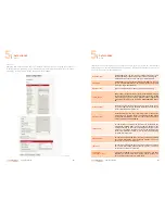
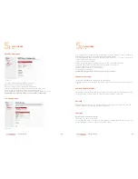
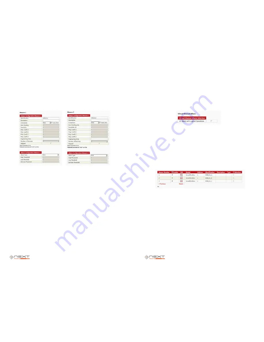
Output Configuration and Alarms 1 & 2
This are channel related settings. The user can specify channel name, a short description,
and data conversion.
Conversion:
Linear:
if sensor output is linear, the systems needs to know Zero Point (Ez) and
Sensibility(S) and Number of Decimals (field will be enabled). The output will be equal to
Sx - Ez
Polynomial:
if sensor output is not linear this allows the user to specify sensor output
curve, and enable Zero Reading (Ez), Poly.Coeff. A, B, C and D and Number of Decimals.
The output will be equal to Ax3 + Bx2 + Cx + D - Ez
Engeneering Units:
to complete data with the right engeneering unit like bar,°C, °F, %HR
and so on.
Number of Decimals: after linear or poly conversion, here are the number of decimal digits
the system will round the value at.
Skipped:
the system will ignore this sensor
Virtual Channel Alarm
This section enables Logical Operations with Virtual Channels Alarm. Virtual Channels sec-
tion allows logial operations between alarms, (AND, OR, XOR, NOT).
Tips
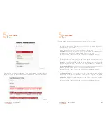
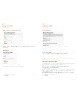
Multiple Sensor in one single Modbus Device
Our System allows the user to connect one single Modbus device providing information
coming from different sensors.
As long as the Modbus slave has a single address and multiple registers (or a combination
of registers for each “channel”). Each “Sensor” named in the Digital Channels can be com-
posed of 2 channels. Each channel is read from a different Register.
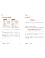
What if a sensor has more than 2 channels?
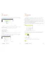
NI400 allows to create another sensor with the
same Modbus address (Fig.9,10,11)
, so user
can select 4 (or more, creating other sensors) registers to read data from.
Pre Measure Actions
(if required) will be set only in first sensor (relative to the Modbus
slave device) and
Post Measure Actions
will be set only in last sensor (always relative to
the Modbus slave device)
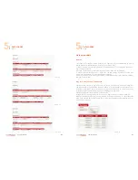
Figure 54
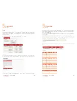
Figure 55
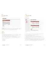
Figure 56
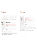
Figure 57
5
5


