background image

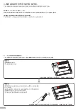
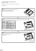
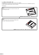
STEP 1 

Hold the receiver button 1 down (about 5 seconds.) until the 

LED begins to Flash.

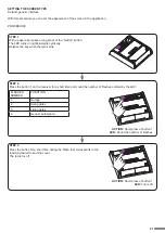
DELETION OF SINGLE 

TRANSMITTER

DELETION OF ALL 

TRANSMITTER SAVED

4.2 - DELETION OF REMOTE CONTROL

These procedures let you delete from the memory transmitters that have already been programmed.

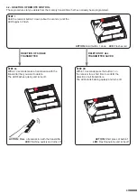
STEP 2a

Within 10 seconds make a transmission with the 

transmitter that you want to delete.

The LED flashes quickly and turns off.

STEP 2B

Within 10 seconds press the button 1 on

the receiver for a short time to confirm the

delection of all transmitters.

The LED starts flashing quickly and turns off.

ACTION:

 Hold tbutton 1 down    

LED:

 Flashes red

ACTION:

 Make a transmission with the transmitter 

LED:

 Flashing quickly and turns off

ACTION:

 Short press of button 1 

LED:

 Flashing quickly and turns off

9

Summary of Contents for PLANO-LOCK

Page 1: ...ces with dry contact inputs e g sectional doors or automated gates Power supply 12 32Vdc or 12 24Vac Output contacts 1A 30Vdc Integrated 433 92MHz radio receiver for remote controls WiFi connection fo...

Page 2: ...NSMITTER SETTING 4 2 DELETION OF RADIOTRANSMITTERS page 8 page 9 5 CONTROL WITH APP ONE SMART 5 1 APP ONE SMART CONNECTION 5 2 USE OF THE APP ONE SMART page10 page 11 6 CONTROL BY VOICE COMMANDS 6 1 C...

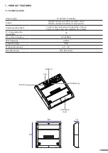
Page 3: ...art function One NC contact 1A 30Vdc for stop function Status signaling inputs 1 input for open automation signaling dry contacts 1 input for close automation signaling dry contacts N of programmable...

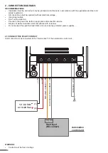
Page 4: ...power line twith an appropriate disconnection device Dispose of waste materials in full compliance with local law Do not exceed the specified load limits and use correctly protected power supplies 2 1...

Page 5: ...n the Plano control unit see paragraph 5 USE VIA APP In order to send start commands from application it is necessary to do the procedure for associating the control unit with the application see para...

Page 6: ...ands The installation can operate with only radio controls or application only Instead to use voice commands at least the App configuration must be completed CONTROL UNIT VOICE CONTROL CONFIGURATION S...

Page 7: ...ation procedure see paragraph 4 3 3 USE VIA SMARTPHONE APP ONESMART The configuration procedures described in paragraph 5 above must be followed to control the lights by smartphone App 3 4 USE WITH VO...

Page 8: ...e compatible multifunctional or generic transmitters ACTION Short press of button 1 LED Turns on red ACTION Make a transmission with the transmitter LED Flashes 3 times 4 MANAGEMENT WITH REMOTE CONTRO...

Page 9: ...Within 10 seconds make a transmission with the transmitter that you want to delete The LED flashes quickly and turns off STEP 2B Within 10 seconds press the button 1 on the receiver for a short time t...

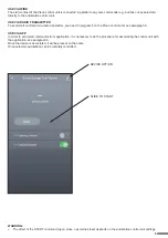
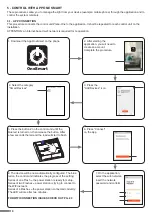
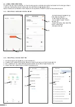
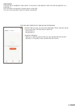
Page 10: ...l the system remotely 5 1 APP CONNECTION This procedure connects the control unit Plano One to the application It shall be repeated for each control unit on the installation ATTENTION an internet base...

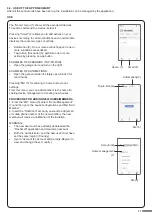
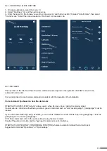
Page 11: ...add members to the home for sharing device management or creating new houses PROCEDURE FOR ADDING NEW USERS MEMBERS 1 From the ME menu 5 select Home Management 7 and then go to the house configuration...

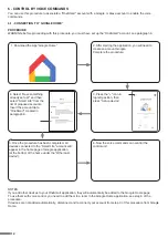
Page 12: ...t the account data OneSmart created in paragraph 6 5 Once the procedure has been completed all devices connected to the Smart Life account will appear in the home page of Google application at the bot...

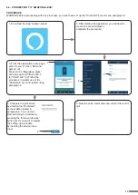
Page 13: ...e of the OneSmart account created using paragraph 6 4 Complete the procedure by entering the OneSmart account data created in paragraph 6 You can then start searching for devices by pressing the Disco...

Page 14: ...ATING A SCENARIO ON ONE SMART 6 3b CREATING A GOOGLE ROUTINE 1 On the Google Home application select Routines 1 2 Create a new routine and insert the phrase you want to pronounce to Add Commands 2 3 O...

Page 15: ...lation Voice command tips based on how the start works START SET AS STEP STEP when it s close open when it s open close during the moving stops If automation is controlled without being visible a gene...

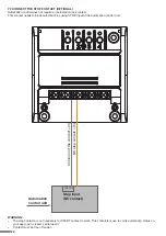
Page 16: ...contact must close this turns on the green light in the app one normally closed contact with no voltage when opening typically this means there is one micro limit switch for when the door opens connec...

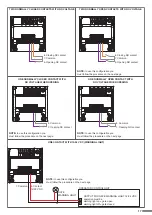
Page 17: ...ct 7 Common 7 Opening NO contact 8 Contact 12 24 VDC 8 Common 7 Common 7 Opening NC contact 8 Common 8 Closing NC contact 6 Opening NC contact 7 Common OPERATOR CONTROL UNIT GATE WARNING LIGHT OUTPUT...

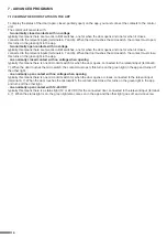
Page 18: ...2 Press the button 1 on the receiver for a short time and count the number of Flashes emitted by the LED FLASHES NUMBER FUNCTION 1 No limit switches 2 n 2 NC contacts 3 n 2 NO contacts default 4 n 1...

Page 19: ...to open the garden lights on when the gate is open notify me 7 2 GRAPHICS OF THE APPLICATION INTERFACE You can change the interface according to the type of automation you are going to control The app...

Page 20: ...omation if limit switches are present closed automation if limit switches are present closed automation if limit switches are present open automation if limit switches are present open automation if l...

Page 21: ...ey when the led is pink STEP 2 Press the button 1 on the receiver for a short time and count the number of Flashes emitted by the LED STEP 3 Press the button for a short time during the Flash that cor...

Page 22: ...on by using STOP input of the automation control unit WARNING The stop contact are not necessary for START contact to work This contatcts is use to verify automation status on your app open closed par...

Page 23: ...se stop contacts to know the status of automation USE THE LIMIT SWITCHES TO CREATE AN AUTOMATION From the Smart screen you can create automation that is automatic events You can enter task in the auto...

Page 24: ...ART application To edit or delete also this parameter reed the procedure PROCEDURE STEP 2 Within 10 seconds make a short press of hidden button The LED 1 Flashes quickly and turns off STEP 1 Hold the...

Page 25: ...these parameters WIFI FREQUENCY BAND some routers generate a network that is set automatically at a frequency of 2 4GHz or 5GHz depending on the device you are connecting with When you are trying to...

Page 26: ......

Page 27: ......

Page 28: ...V1 0 Nexta Tech company brand of Team srl via G Oberdan 90 33074 Fontanafredda PN Italy Ph 39 0434 998682 Email info nexta tech com Web www nexta tech com...

Reviews: