17
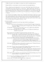
triggering factor. Press ALARM RESET to cancel the warning and perform the OPR calibration operation.
The recipe operation needs to be loaded again.
4) EMO button is triggered - After confirming that the safety condition has been eliminated, pull the EMO button
and press the motor power on. If you need to move the press head out of the current position, press the Z
button to move it. Press ALARM RESET to eliminate the warning and performs a OPR calibration operation.
The recipe operation needs to be loaded again.
5) Analysis of abnormal item -
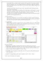
1) The press head is not positioned - the safety handle has not been pulled down or the trigger switch has
malfunctioned.
2) Work overtime - Error in parameter setting of press parts, resulting in overtime of work time or setting
of work time parameters too small.
3) Force error - actual force exceeds lower force limit.
* PCB hole is too large
* Connector specification error
* The setting range of the lower limit value is too small
4) Force error - actual force exceeds upper force limit.
* PCB hole is too small
* The setting range of the upper limit value is too small
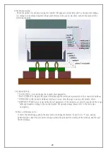
* Pin bending deformation did not lead into the hole
* Distance parameter error
* Connector specification error
* Jig error
5) Distance error - Generally occurs when the force value is greater than the upper limit value.
6) Work interrupt - Other factors cause the sensor to be triggered to stop the job
* Push back the safety handle during operation
* The emergency stop button is triggered
* Servo up and down limit sensors are triggered during operation
* Safety sensor is triggered
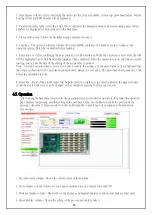
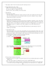
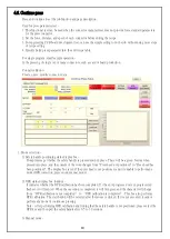
8. Press product data display column -
Display the product serial number, product name, part number, lot number, and PCB number that are now pressed.
The product serial number is loaded or entered by the scanner after the barcode is loaded or entered. Each time a
PCB is completed, the column will be cleared. If no bar code is scanned, the job cannot be executed (the bar code
check function is checked on the parameter setting page).
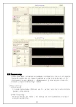
9. Curve display column - Shows actual force and distance being press.
1) Chart description -
* Orange - Distance setting
* Blue - Force limit setting
* Red - Force and distance correspond to the actual value
* Y-axis - Force (N)
* X-axis - Distance (mm)
2) Curve description -
When the press head is pressed, there will produce a force-distance composition of a red curve, starting from
the lower left corner of the graph 0 points. With the distance increases, the force enter the PCB with the eye
of needle, resulting in curve rise and fall changes. The distance to the end of the limit the line stops and
returns to complete the pressing operation.

