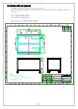
background image


Summary of Contents for LPM3

Page 1: ...1 LPM3 Manual Company Nextronics Date 2018 04 16 Version LPM3 A0 ...

Page 2: ...3 4 In production confirmation 3 5 After production confirmation 10 10 11 11 11 11 4 Software Operation Interface 4 1 User interface introduction 4 2 User change 4 3 Password setup 4 4 Load recipe 4 5 Operation 4 6 Continue press 4 7 Edit recipe 4 8 Process log 4 9 SPC 4 10 Parameter setup 12 12 13 14 14 15 16 19 19 22 23 26 28 30 5 Maintenance 31 6 Appendix 6 1 Tool and accessory 6 2 Machine tabl...

Page 3: ... protection when operating the equipment 2 Always ground the power supply properly to prevent electric shock 3 Always maintain proper power connection to prevent danger 4 When performing equipment maintenance make sure to turn off the power switch and disconnect the power cord from the power supply always 5 Do not wear loose clothing or jewelry that may get caught in moving parts of the device 6 D...

Page 4: ...is true and is false when the controller detects a problem 2 The Acroloop servo controller PLC output servo controller has an internal program to monitor servo operation and disconnect the EMO circuit when a problem is detected 3 Motor overload relay which is a temperature sensitive motor overload protection device monitors the motor over current condition If the motor current is consumed for a lo...

Page 5: ...ss fit machine away from the load bearing plate lift and place it on the work table Make sure that the placement table must be leveled and pay attention to the location of the keyhole 4 Lock and adjust the machine 1 The mounting hole size of the device is 310mm 450mm and the mounting hole diameter is 13mm 4 holes 2 When the equipment is hung and placed 50 100mm away from the desktop stop first the...

Page 6: ... see the left picture below 2 Open the main power switch of the front panel and the power light will be on to start the machine and confirm that the computer is started below right picture 3 Press the green light button on the left side of the box to start the motor lower figure below 4 The computer will automatically enter the login screen or click on the replacement operator screen function key ...

Page 7: ...ion are labelled on the back panel of the machine 2 Power supply 220V AC single phase Weight 550 kg Press fit force 5000 kg Press fit distance 80mm Machine size 1100L x 980W x 1400H 50mm 3 End of life cycle It is suggested returning the machine to Nextronics after end of life 1400mm ...

Page 8: ...or 5 Button box 1 Emergency off button EMO Use for emergency stop 2 Z axis control button In the manual mode the left button controls the Z axis down and the right button controls the Z axis up 3 Start button In both press fit mode and recipe mode both hands press simultaneously to start the job 6 Safety handle Increase space and protection when replacing product fixtures 7 Work Lights Optional Pr...

Page 9: ...it process control The force and distance control can be precise and cross protected so that the press fit process can be effectively monitored 1 Set the upper and lower limits of the standard force so that it corresponds to the range of variation due to the variables of the pins and the PCB Exceeding the upper limit of the monitoring force may damage or cause abnormal set point protection and the...

Page 10: ...ch is located on the lower left corner of the front panel Turning to the OFF position will disconnect all system power source Turn the knob to the ON position to start the machine the knob lights up below pic 3 The motor start switch lower left is located on the left side of the box with green cover button The button lights up and start the motor after pressing it It must be started when restartin...

Page 11: ...hether the upper and lower tools are used 4 Confirm the direction of the press head is 0 degrees or 90 degrees below 5 Confirm the operator 3 4 In production confirmation 1 Serial number input 2 Press position 3 The connector corresponds to the upper tool 4 Connector pre insertion holes in place without tilting 5 The tool is placed and fitting the connector 6 Condition after press fit is completed...

Page 12: ...atabase It can assist recipe editing at the same time and load the completed parameter data to recipe edit instantly Note This function is not suitable for work order production this process does not record the press data and curve 3 Load Recipe The production call corresponds to the lot number of the backplane and the completed pressing program will be established to call load and perform the fun...

Page 13: ...rt up settings it can also change the operators for tracing on quality 4 2 User change A login window will appear on the screen displays for user interface Only the User change option can be used in this state Enter the user name and password in the window and then press Enter to enter the user interface The user can use the function according to the permissions The functions that can use permissi...

Page 14: ...ermissions Delete Click to delete the user name then click Delete to delete the user 4 4 Load recipe Selection confirmation and execution of the pressing process for production 1 Status columns Shows the status of the program as Load Execute Wait Error status 2 Open file Click on OPEN FILE key to selectt the recipe file for the backplane product that has been created The part number field displays...

Page 15: ...ed in order to ensure the accuracy of the press distance it is confirmed that the origin calibration will be performed synchronously during the execution The personnel shall pause the work before the calibration is done 8 Reset key Reset of the product must first be performed the original recipe must be deleted the page field data should be cleared the recipe can be changed or the continuous press...

Page 16: ...lthough the speed is slow when performing OPR calibration please keep people away from the machine to prevent injuries 3 Abnormal item column When an abnormality occurs it corresponds to the abnormal item column and abnormal statuses such as time stress and distance are displayed as red abnormalities The pressing parameter message stays at the current pressing sequence number After confirming the ...

Page 17: ...or Jig error 5 Distance error Generally occurs when the force value is greater than the upper limit value 6 Work interrupt Other factors cause the sensor to be triggered to stop the job Push back the safety handle during operation The emergency stop button is triggered Servo up and down limit sensors are triggered during operation Safety sensor is triggered 8 Press product data display column Disp...

Page 18: ...nd the pressing position are displayed Press display status 1 The serial number box ready to be pressed to the current position will be displayed in green and the Status column will be displayed when replacing a new one 2 The serial number box that is being pressed to the current position will be displayed with a flash and the job will be displayed in the Status column 3 Once the single point pres...

Page 19: ...andle is pressed down in place There will be a green bottom when pressed into place and the content of the word changes from Press head not positioned to Press head has been positioned The display box is red if the press head is not positioned and it is unable to perform any mode OPR correction press mode manual mode 2 OPR status display box button It indicates whether the OPR calibration has been...

Page 20: ...enter a single cycle pressing operation The box will display the reverse color as the current mode state The machine starts the pressing operation and both hands need to press the start switch at the same time Perform the pressing procedure 5 ALARM RESET When the emergency stop button is triggered the motor will stop operation and the power is turned off After removing the abnormality and restorin...

Page 21: ...N Force lower limit the minimum force for the connector press force the default value is 240N and the minimum setting value is 0N Distance mm unit is mm minimum setting unit is 0 01mm the default value is 0 mm Standby point In order to improve the working efficiency after each pressing cycle is completed the minimum clearance required for the press head to reach the upper fixture is controlled so ...

Page 22: ...ters to the connector s database CONN_DB Link connector database interface you can enter the page to query add modify delete EDIT RCP With the new recipe table the test parameters of the connector are directly exported to the recipe table and loaded according to the required points For operation usage please refer to the edit recipe description 4 Force and distance curve It shows the monitoring gr...

Page 23: ... a general bottom tool it refers to the limiting plate f Set pressing serial number block Check the POSITION Move the mouse to the pressing position editing area and click the left mouse button at the desired pressing position A yellow square will be created with the press number The number above indicates the pressing sequence Click on the desired press for location and order At the same time in ...

Page 24: ... the distance pressed into the PCB by the connector Note The TOTAL_DISTANCE needs to be input first and the rear field can be calculated automatically Otherwise the connector part number selection data is loaded first and the subsequent field value is not the correct value It is necessary to perform b steps once after entering the TOTAL_DISTANCE and recalculate the contents of the subsequent colum...

Page 25: ... corner to select the recipe table that needs to be edited After the file is opened the edit page will bring out the previously set data and then enter the changes according to the required pressing sequence and column data and then archive the file name For the change the file name is newly created There will be no warning window and it can also be used in the copy recipe editing of a later versi...

Page 26: ...t is deformed to a steady state the connector will not bounce default 0 4 sec in sec 12 P1_POS The first switching point is also the position of the pre press point and the distance value is from 0 to P1 point of the press head The unit is mm 13 P1_SPEEED The speed of the standby point to the point of P1 unit mm sec 14 P1_STAY The time paused from the connector is held to the P1 preload point The ...

Page 27: ... YY year MM month DD day hh hour mm minute ss second 2 After the time period is set click the REFRESH button the search for the items in the set time period will be performed and displayed in the conditional option area 3 In the condition area click the needed item the content of the condition field will be black and then click the data in the display area To search for display data you can click ...

Page 28: ...set and the input is completed click on the SEARCH button The production data window will appear as shown below The data will be listed by clicking the display item 6 Data content can be exported to CSV format for Excel which can be used for editing statistics production report or customer data Use the OUTPUT CSV FILE button in the upper left corner ...

Page 29: ...e are two sets of condition data for statistics Condition 1 The statistics of the force of a certain PCB s pressing position on the same worksheet is set in the same way as the yield statistics page Condition 2 For the same part number within a certain period of time the force of a certain PCB press position statistics data set in the same way as the yield rate statistics 1 After the condition dat...

Page 30: ...cording to the requirements of the textual description of the page The adjustment is completed before the setting is completed 1 Press parameter page 1 Security settings It is to protect the press parts and PCB from damage The range of parameter values for each control during pressing is a further protection 2 Work overtime setting The unit is milliseconds ms It means the press head drops from sta...

Page 31: ...et value is the surface that does not interfere with the top side of the pressed object The setting unit is mm 2 System parameter setting 1 Path setting Set the data storage paths which are the path settings of the related files such as the recipe table file the edited recipe file the SPC statistical export data file the pressed generated graph file the production record production data file and t...

Page 32: ...d or soiled This must be checked once a year 3 Lubrication Lubricate the X Y Table Y axis linear slides X axis ball guides Use light oil or 25W 30W machine oil to lubricate the Z axis screw and guide rod of the press head s cranks Use lithium soap based lubricating oil lubricant grease The viscosity index range is above 90 Cst ISO VG 90 when lubricating oil is 40 C 4 X Y Table Y axis track Push th...

Page 33: ...or loosen screws 2 C spanner To adjust the height of the press fit machine 3 Phillips Screwdriver To fasten or loosen screws 4 Allen Wrench To fasten or loosen different size of screws 5 Adjustable Wrench To fasten or loosen different size of screws and to adjust the machine s tripod for leveling ...

Page 34: ...perators between 155cm and 170 cm tall Please adjust the table based on your need Size 1 1500mmX900mmX700mm Size 2 800mmX 800mmX700mm Below drawing is for 1500mmX900mmX700mm REV A0 REV A0 PART DWG NOTES 1 NOTES 2 xxx xxx xxx XXX XXX XXX 1 1 1 2 X1 重型工作桌 Zale 07 27 2009 SET NOTES 1 Material 桌面 高密度纖維板 桌體 SS41方管2 2 2t 市售品 2 表面烤漆處理 白百合 ...

Page 35: ...ase contact our sales window or please call us for service Company Nextronics Engineering Corp Address 2F No 31 Lane 169 Kang Ning Street Hsi chih District New Taipei City Taiwan Telephone 886 2 66162000 Website www NextronGroup com ...

Page 36: ......

Reviews: