background image

7

v.12/2020

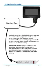
First attach the pendant cable between the Pendant and 
the control box. Then plug power cord into a power 
source. Using a switched power strip is highly 
recommended. As well as providing surge protection for 
your tool, it provides another method for shutting off the 
machine in case of an emergency. 

IMPORTANT 

– DO NOT plug in and turn on the 

power before all the motor cables have been 
attached. DO NOT attach or detach motor cables 
when the control box is powered up as this can 
damage the electronics and is not covered by the
warranty.

Control Box

Pendant Cable Connection

Summary of Contents for SHARK LCD

Page 1: ...SHARK LCD Pendant Control User s Manual ...

Page 2: ... subject to change without notice The most recent version of this manual can be found at www NextWaveCNC com downloads links Next Wave CNC LLC info nextwaveCNC com 600 W Boundary St Perrysburg Ohio 43551 USA 419 318 4822 Please read this manual carefully It provides important setup and operational information for your SHARK CNC and software This manual has been written with the assumption that you...

Page 3: ...og Speeds 19 LCD Brightness LCD Beep Sound 20 Noisy Environment Reverse Spindle Polarity 21 Model number 22 Display Metric 23 Safe Height 24 File Char Delay 25 Apps Menu screen 27 Touch Plate Calibration 28 Virtual Zero 30 Boundary Monitor and Center Finder 47 Job Array 48 Homing X Y Axes 50 Digitizer 55 Laser 57 4th Axis 59 Factory Restore Unregister LCD Reset LCD 60 About LCD About Controller 60...

Page 4: ...e CNC shipping prepaid with proof of purchase and within the warranty period Next Wave CNC disclaims all other express or implied warranties including fitness for a particular purpose Next Wave CNC shall not be liable for death injuries to persons or property or incidental consequential contingent or special damages arising from the use of the SHARK LCD Pendant Warranty Safety Read and follow all ...

Page 5: ...ller information below To locate the information see the pages listed below Controller Box Serial Number see page 60 _______________________________________ LCD Pendant Serial Number see page 60 _______________________________________ LCD Pendant Unlock Code see page 10 _______________________________________ Technical Support If you need technical assistance with your SHARK LCD Pendant please vis...

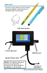
Page 6: ... Pendant cable Connects to control box Z Touch plate port The touch screen buttons can be activated using your fingertip a pencil eraser or a soft tipped stylus not included NOTE The Pendant cable has a special pin configuration A standard VGA cable can not be substituted it will not work ...

Page 7: ...oviding surge protection for your tool it provides another method for shutting off the machine in case of an emergency IMPORTANT DO NOT plug in and turn on the powerbefore all the motor cables have been attached DO NOT attach or detach motor cables when the control box is powered up as this can damage the electronics and isnot covered by the warranty Control Box Pendant Cable Connection ...

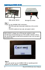
Page 8: ...n the control box The SD machines have only one power switch Step 2 Once you power up your SHARK CNC an opening screen appears on the pendant Click Continue Main power Switch IMPORTANT Always turn off the power switch s when connecting or disconnecting any of the cables Failure to do so can cause damage to electrical components and is not covered by the warranty ...

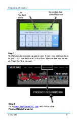
Page 9: ... and click on the Product Registration tab XXXXX XXXXX Controller Box Serial Number LCD Pendant Serial Number Step 3 The Registration screen appears next It lists the serial numbers for your LCD Pendant and Control Box Record these numbers on Page 5 of this manual ...

Page 10: ...he form Registration cont Step 6 An Access Code appears on your screen This code will also be sent to the email you entered in the registration form Record your Unlock Access Code on page 5 of this manual 4XXX0 XXXX2 XXXX2 Step 7 Use the number keys on the Pendant to enter your Unlock Access Code Press Submit This unlocks the Pendant 4XXX0 ...

Page 11: ...ocked Registration cont Step 8 The Calibration Screen appears next Follow the on screen directions to complete the calibration Touch screen to continue The Calibration Screen also appears after a firmware updates The screen can also be opened by holding your finger on the screen while turning on the control box ...

Page 12: ...s designed to help control dust add safety and reduce machining noise The enclosure is made with an aluminum frame acrylic panels and steel connectors The hinged access door with magnetic catch allows for easy material removal or bit changes There are pre drilled 3 hole for cords The case to be placed on any flat surface The enclosure ships flat assembly is required SHARK machine enclosure ...

Page 13: ...ble tap Mv 0 0 0 Moves the X Y and Z axes to their zero positions 4 Zero xyz Press to zero the XYZ axes The axes position fields 1 will all reset to 0 000 5 Setup Press to access the Setup submenu see page 18 6 Apps Press to access the Apps submenu see page 27 7 USB Glows blue when a USB drive is inserted into the Pendant Press to access the toolpath selection screen see page 38 8 Refresh Press th...

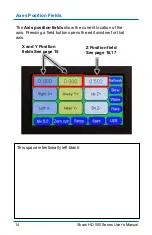
Page 14: ...Axis position fields show the current location of the axis Pressing a field button opens the edit window for that axis Axes Position Fields X and Y Position fields See page 15 Z Position field See page 16 17 This space intentionally left blank ...

Page 15: ...its current zero position 5 Set After entering a new location in the position field press this button to apply set the new location The position also changes on the Main Control Screen 6 Number keypad Use these keys to enter a new location in the position field 7 C Press to delete the information in the position field 8 Location Pressing this key to enter the current axis location into the positio...

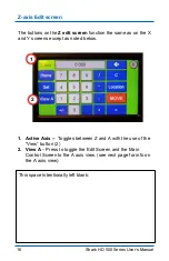
Page 16: ... with the use of the View button 2 2 View A Press to toggle the Edit Screen and the Main Control Screen to the A axis view see next page for info on the A axis view The buttons on the Z edit screen function the same as on the X and Y screens except as noted below This space intentionally left blank ...

Page 17: ...ntrol Screen to the Z axis view 3 Position field The A axis position field displays degrees of rotation The other buttons function the same as those in the XYZ edit screen The A axis is used to set the rotational position on the Rotary 4th Axis accessory 4 4 A axis controls also appear in the Main Control Screen The A axis position field displays degrees of rotation ...

Page 18: ...ee page 20 See page 20 See page 21 See page 21 Scroll down arrow See page 22 See page 23 See page 24 See page 25 The Setup submenu contains options for controlling how the Pendant functions Press a submenu item to open the settings screen for that option To return to the Main Control Screen press X Press in the upper right corner ...

Page 19: ...hown at the tope of the window Press the current speed setting field opens the keypad shown below Jog Speed Settings Current Speed setting Maximum system speed Use the keypad to change the Jog Speed setting Press OK to save the setting Press X to exit this window Exit button NOTE The maximum system jog speed is 200 inches min ...

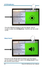
Page 20: ...ess setting to open the keypad Use the keypad to adjust the LCD Brightness Press X to exit the current screen Beep Sound Press the sound setting field at top right to open the keypad Use the keypad to adjust the volume of the Beep Sound Press X to exit the current screen ...

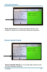
Page 21: ... Noisy Environment is an advanced feature used by Tech Support to resolve any rare electrical interference problems Reverse Spindle Polarity Reverse Spindle Polarity is a touch plate legacy feature used by only a few older machines ...

Page 22: ...trols several default setting on your SHARK CNC such as motor rotation and XY machine orientation Verify the model number setting for you machine using the chart below Also check this setting after you do a Control Box or Pendant firmware update Model Number ...

Page 23: ...23 v 12 2020 Display Metric toggles the position fields between millimeters and inches Display Metric mm Position fields set to metric mm ...

Page 24: ...ual Safe Height The Safe Height setting controls how far the router bit rises above Z zero when you press the Mv0 0 button You can adjust the Safe Height by pressing on the setting field at the top of the screen This opens the keyboard ...

Page 25: ...by Tech support when troubleshooting special setups Do not change this Explore and expand your CNC creativity with the book the shows you how Available from your Next Wave CNC distributor or online at www NextWaveCNC com CNC Router Essentials Get started right with the book that shows you how ...

Page 26: ...o Touch Plate is available from your local Next Wave CNC distributor or online at www NextWaveCNC com Z Zero Touch Plate automate your Z zeroing process with accuracy and convivence The Standard model is 2 in diameter The Mini model is 1 in diameter and is an add on to the Standard model ...

Page 27: ... down arrow See page 57 See page 59 See page 60 See page 60 See page 60 See page 60 See page 60 The Apps submenu contains special functions for calibrating operating your tool and when using optional accessories Press a submenu item to open the settings screen for that option Press X to return to the Main Control Screen ...

Page 28: ...ies User s Manual Touch Plate Calibration Press Press To Open to open the submenu Pressing Run Z Calibration to initiate the Z touch plate routine This function is the same as pressing the Plate button on the main screen ...

Page 29: ...tting The default setting of 10 works well for most situations The default Plate Thickness setting of 375 corresponds to the standard thickness of Next Wave touch plates This setting can be changed if you use a tough plate with a different thickness or if you want the Z Calibrations routine to calibrate a little thicker or thinner than the actual plate thickness ...

Page 30: ... match the Z height variations caused the uneven board or machine table The Virtual Zero map is automatically saved and can be used multiple times on the same part when different router bits are needed to complete the project The Virtual Zero map is saved until you redo it or turn of the control box Mapping the surfaced of your material with Virtual Zero involves several steps so it s recommended ...

Page 31: ...31 v 12 2020 Virtual Zero cont Step 1 In VCarve set the Z Zero Position to the Material Surface and the XY Datum Position to the center of your project Step 2 Create your project design ...

Page 32: ...2 Shark HD 500 Series User s Manual Virtual Zero cont Step 3 Create and Save Toolpaths to your USB drive In this example we need two toolpaths to complete the project Step 4 Insert USB drive into Pendant ...

Page 33: ...open the Virtual Zero settings screen Step 6 Select your Touch Source The Plate touch plate option is commonly used because most SHARK owners already own the touch plate but the Probe digital probe also works well Press the field at the upper right to change the selection Virtual Zero cont ...

Page 34: ...10 works well for most situations To change the setting press on the settings field in the top right Step 8 Set the Scan Width X and Scan Length Y for the area you want to scan This is typically the size of your cutting area see next page Note Setting the Scan area is not required since you can also use the VCarve file size as the scan area This is covered on pages 39 and 40 ...

Page 35: ...but it s usually most useful to limit it to approximately the cutting area for your design X Scan Width Y Scan Height Step 9 To Enable Virtual Zero press the settings field in the upper right and entering 1 for YES Press X to exist this screen and return to the main screen ...

Page 36: ...500 Series User s Manual Virtual Zero cont Step 10 Install the router bit Move the router bit to the center of the pencil mark Press Zero xyz to zero the X and Y axes tip of router bit to the center of the material ...

Page 37: ...37 v 12 2020 Virtual Zero cont Step 11 Use the Plate function to zero the Z axis to the top of material ...

Page 38: ...Manual Virtual Zero cont Step 13 Review the header information screen if it looks OK press the Next button to continue Step 12 Select the toolpath file that you want to cut In this example we re starting with VZ Logo 01 V Carve tap ...

Page 39: ...ro scan routine Press No if you don t wish to use Virtual Zero for this tap file The Existing Points button is greyed out because no points have yet been captured Step 15 Select the Scan Region See the next page for information on the differences between File Specifies and Current Region ...

Page 40: ...s region equals the Job setup less 1 inch This provides a half inch of clearance around the material to assure the scan area stays within the boundary of the material and to allow some room from clamps The Current Region uses the Scan Area specified in the Virtual Zero app ...

Page 41: ...s It repeats the routine five times in order to capture the four corners and center point of the scan area See below Step 17 The amount that the captured point varies original Z zero position appears next to each point After scanning a point you can Redo Point or press Next to continue Virtual Zero cont ...

Page 42: ... screen appears run the file as usual Notice that a small green V appears in the top right corner of the screen This signifies that the file is using Virtual Zero After the first file is done running press the X to return to main screen Step 19 The first toolpath is now complete ...

Page 43: ...d and install the next bit In this example we re using a 0 25 inch endmill bit for the next toolpath Step 21 Select the next tap file that you want to run for your project In this example we re using the VZ Logo 02 Cutout tap file Step 22 Review the file information screen and click Next ...

Page 44: ...er s Manual Step 23 Since we ve already captured the points for this project press the Existing Points button on this screen Step 24 Selecting Yes launches the Touch Plate Z calibration routine for the new bit Virtual Zero cont ...

Page 45: ...tual Zero points Step 26 This completes the Virtual Zero routing for this project but you the Virtual Zero map can be reused as many times as you need to for this setup until all your toolpaths have been run If you install a new piece of material you need to redo all the Virtual Zero points because no two boards are the same Virtual Zero cont ...

Page 46: ...aveCNC com Starter sets General purpose sets 1 8 dia tapered ball nose 1 4 dia 60 deg V bit 1 4 dia Spiral Upcut Router bits Find the right bit for your project Bits are available in a variety of sizes and shapes and as singles or sets V Bits straight bits upcut spirals carving bits small diameter bits and coated long lasting bits 1 2 dia 90 deg V bit ...

Page 47: ...47 v 12 2020 The Boundary Monitor is still being developed and will eventually operate similar soft stops Boundary Monitor The Center Finder is a discontinued feature Center Finder ...

Page 48: ...48 Shark HD 500 Series User s Manual Job Array Use the Enable Job Array setting to toggle the app ON an OFF The Job Array app allows you to create duplicate parts from a single design ...

Page 49: ...quals the distance between X Y datum points for each part Also see the details below The of Runs and Rows controls the number of copies in the X and Y direction Offset with Lower Left XY datum Offset with Center XY datum Job Array cont ...

Page 50: ...e you run a file It provides a repeatable reference point that is particularly useful when using jigs or when you need to run a cutting file from a precise repeatable location NOTE The Home X Y Axis app only works with the SD120 HD500 HD510 HD520 machines The SD100 and SD110 do not have the required sensors nor can the sensor be added to the SD100 or SD120 Selecting either Home X Axis or the Home ...

Page 51: ...51 v 12 2020 You must be within 4 inch of the left side and the front of the machine when you run the routine 4 4 Center of Z axis router bit Top view of Shark T track table Home X Y Axes cont ...

Page 52: ...be centered over the Machine Home location and the Pendant will read X0 Y0 X0 Y 0 Top view of Shark T track table Center of Z axis router bit The default Speed setting of 10 works well but it can be adjusted by pressing the settings field at the top and entering a different number Home X Y Axes cont ...

Page 53: ...atum location in your VCarve Job Setup NOTE The Offset number must be a negative number After setting the Offset amount run the Home X Y Axis routines When the homing routines finish running the X Y axis will be positioned at the Machine Home location see below but the X and Y position fields on the main screen will reflect the negative offset amount see next page 12 000 X 12 Y 12 Home X Y Axes co...

Page 54: ...hark HD 500 Series User s Manual X 12 Y 12 X0 Y0 After the Offset calibration completes press Mv 0 0 to move the X Y axes to the new project zero location see below Home X Y Axes cont XY Offset option cont ...

Page 55: ...zer accessory is used to map the shape of your project The scan is used to create a copy of an existing carving or in conjunction the Virtual Zero app page 30 See the Digitizer Owner s Manual for complete use and operating information ...

Page 56: ...ule accessory from Next Wave CNC Available from your local Next Wave CNC distributor or online at www NextWaveCNC com Laser Module Available in 2 or 7 watt power The Laser Module enables you to create detailed laser engraved photographic engravings images and lettering ...

Page 57: ... This allows you to verify the position of the laser without burning the material Minimize Over Burn reduce the laser intensity when the machine slows down around corners Does not apply when burning raster files See the Laser Owner s Manual for complete use and operating information ...

Page 58: ... from Next Wave CNC Available from your local Next Wave CNC distributor or online at www NextWaveCNC com Mini Rotary 4th Axis Works like a wood lathe but can also carve intricate patterns and designs in your CNC project Excels at turning pens and tool handles ...

Page 59: ...4th axis accessory selection screen 3D Printer discontinued Lathe A use this setting for the current standard rotary 4ht axis accessory Lathe B use this setting for 4th axis accessories manufactured before 2015 Mini use this setting for the current Mini rotary 4ht axis accessory 3D Mode Prime Speed Prime Step associated with the 3 D printer and no longer used ...

Page 60: ...ant and the next time it is powered up you will need enter the Access Code to unlock the Pendant Reset CNC functions like the Refresh button the main screen page 13 About LCD displays Pendant serial number and firmware information see next page About Controller displays Controller control box serial number and firmware information see next page Misc Apps and Info screens ...

Page 61: ...61 v 12 2020 LCD Serial Number Controller Serial Number LCD Firmware Version Controller Firmware Version Controller Model Number About Screens ...

Page 62: ...s with a soft cloth and computer screen cleaner or camera lens cleaner Use canned air to clear the dust out of the USB port and around the edge of the screen Use a folded piece of paper to clear wood chips from the edge of the screen Maintenance Firmware updates For information on how to update the firmware on your Pendant and Control Box visit https www nextwavecnc com frequentlyaskedquestions ...

Page 63: ...w more functions and screen visuals than the LCD Pendant Controlling your SHARK using the Ready2Control does however requires you to connect your computer directly to your SHARK Control Box Ready2Control can be connect at the same time as the LCD Pendant and you can toggle between the two as needed More information about Ready2Control can be found at www NextWaveCNC com Control Box ...

Page 64: ...SHARK LCD Pendant Control Owner s Manual 12 01 20 80007 ...

Reviews: