background image


DCU20

 User Manual rev. 21 

Page 11/29 


Temperature (T) measurement

: The battery temperature is monitored through an optional 

temperature sensor (

P/N: WNTC-2MT

). The battery charger takes into account the battery 

temperature  and  provides  a  temperature  compensated  charging  voltage.  In  case  of  over 
temperature the system disconnects the battery to prevent damage. 


Coulomb  counter

:  It  allows  having  a  quick  estimation  of  the  remaining  battery  capacity 

and consequently the available backup time. 


Deep  discharge  protection

:  It  protects  against  the  deep  discharge  of  the  battery  which 

can lead to its irreversible damage. 


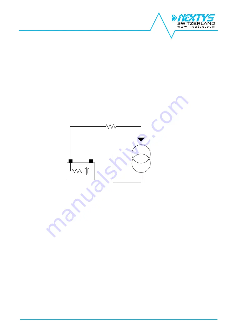
3.5  Battery resistance measurement 

The battery 

internal resistance

 (Ri) is measured by injecting a defined AC current through a 

constant 

current source

 (CCS) in the battery and measuring the AC voltage drop across the battery terminals. 

The principle is represented in Figure 7. 
The injected AC current I(AC) is flowing also through the  connectors resistance - 

“Rcables”. 


Ri

+

-

Battery

Rcables

Constant

Current

Source

(CCS)

I(AC)


Figure 7: Internal resistance measurement 


Without  using  the  battery  sense  connection

  as  shown  in  Figure  9  the  AC  voltage  drop  is 

measured across the battery connection terminals on the DCU20. The measured resistance will be in 
this case: 

Rmeasured=Ri+Rcables. 

When high Ah batteries and / or small and long cables are used 

Rcables


can be > 

Ri

. Anyhow a  connection problem as for  example a loose contact  can be detected by this 

measurement method. 
 

By using the battery sense connection 

(a “Kelvin” type connection)

 as shown in Figure 10 the 

AC voltage drop is measured directly at the battery terminal. In this case the measured resistance is 

exactly the battery internal resistance Ri

, independently on the cables length and size. 

It is recommended to use this method to have an accurate reading of the battery internal resistance 
and thus an accurate prediction of the battery health status. 
If the battery sense cables length is > 2m it is recommended to twist the 2 wires together in order to 
increase the noise immunity. 
 

3.6  Battery charger 

The battery charger supports 

various chemistries

 such Lead-Acid,  Nickel, Lithium and every other 

battery chemistry assuming that the charging voltage and charging current values are provided by the 
battery manufacturer. The charging algorithm is shown on Figure 8. Other charging algorithms can be 
implemented by request. 
The user must set to the unit the following parameters to allow the charger to perform correctly: 

  Battery chemistry: selectable between Lead-Acid, Nickel, Lithium (see §5.2.2). 

  Battery nominal voltage: between 12V and 28V (see §5.2.3). 

Summary of Contents for DCU20

Page 1: ...DCU20 User Manual rev 21 Page 1 29 DCU20 12 24V 20A High Performance DC UPS User Manual...

Page 2: ...ication in which the failure of the NEXTYS product could create a situation where personal injury or death may occur Should Buyer purchase or use NEXTYS products for any such unintended or unauthorize...

Page 3: ...ge 18 5 2 2 Battery chemistry 18 5 2 3 Battery nominal voltage 18 5 2 4 Battery capacity 18 5 2 5 Battery charge voltage 18 5 2 6 Battery charge current 18 5 2 7 Battery deep discharge voltage 18 5 2...

Page 4: ...Manual rev 21 Page 4 29 5 3 3 Name 22 5 3 4 Power ON cycles counter 22 5 3 5 Operating time 23 5 3 6 Battery installation date 23 5 3 7 Battery operating time 23 5 4 Logs 23 5 5 Wizard 23 6 Events and...

Page 5: ...ays are present for remote monitoring See 3 1 for more details 5 Inhibit input A signal between 5VDC and 30VDC applied to this input inhibits the backup function this input is programmable to be activ...

Page 6: ...time Remote input to inhibit the UPS function Connection of a battery thermal sensor optional Integrated data logger with time stamp all events errors are logged in the internal memory and downloadabl...

Page 7: ...onitored by the microprocessor In case of a power outage the battery is connected to the load instantaneously through an active switch reducing the power loss to a minimum The product offers additiona...

Page 8: ...the recharge time avoiding discharging the battery when not needed During backup the internal Coulomb counter is used to give an estimation of the residual charge of the battery this information is g...

Page 9: ...FF signal PC status Output voltage Output current Input voltage T1 T2 T3 T4 T3 E3 E1 E2 E4 Ioff Figure 5 Shutdown and restart chart Parameter Name Description E1 Backup Power failure on the line happe...

Page 10: ...below the Ioff current threshold to trigger the automatic PC restart PC supply ON OFF ON cycle Ioff PC OFF detection current threshold User settable 5 2 27 Current threshold used to detect PC OFF sta...

Page 11: ...inals on the DCU20 The measured resistance will be in this case Rmeasured Ri Rcables When high Ah batteries and or small and long cables are used Rcables can be Ri Anyhow a connection problem as for e...

Page 12: ...rmined amount of time The value is automatically calculated by the device For Nickel batteries only the following conditions are also checked Temperature Cutoff TCO The battery temperature if higher t...

Page 13: ...procedure is used to turn ON the UPS to operate during a power interruption or to determine if the UPS will not turn ON due to a bad input power This practice is also a method to see if the battery co...

Page 14: ...the wiring polarity Please check the load and the power supply are rating compliant 4 3 Connecting the battery The DCU20 must be connected to a battery with nominal voltage between 12VDC and 28VDC wit...

Page 15: ...input fails with no battery backup The polarity of this input can be changed as explained in 5 2 15 4 6 Dry contacts 2 relays dry contacts are provided on the DCU20 Connect the 2 relays dry contact u...

Page 16: ...ce settings are configurable from this menu Use the UP DOWN KEY to navigate through the parameters Press the OK KEY to enter exit the editing mode In editing mode use the UP DOWN KEY to change the hig...

Page 17: ...nges from green to red and a message with the cause appears Battery The battery voltage current temperature resistance and charge are shown in this section In case of problems with the battery the bac...

Page 18: ...Battery capacity Used to set the nominal battery capacity of the battery The internal Coulomb counter uses this value to indicate the state of charge of the battery Default 2Ah Range 1 2Ah 150Ah Resol...

Page 19: ...0 Resolution 1 5 2 11 Battery maximum temperature An optional external temperature sensor P N WNTC 2MT is required Used to set the maximum temperature at which the battery can operate safely If the me...

Page 20: ...backlight Used to set the LCD screen backlight Default 2 Range 1 10 Resolution 1 5 2 18 Screen timeout To save the LCD backlight the system dims the LCD after the defined timeout value Default 5min Ra...

Page 21: ...backup and PC shutdown command sent by POWERMASTER see 3 3 for details Default 0s Range 0s 60min Resolution 1s 5 2 25 PC shutdown time Delay between start of PC shutdown and output power OFF see 3 3...

Page 22: ...arity and event associated with the relay See 3 1 3 for more details 5 3 Info While in the info menu use the UP DOWN KEY to navigate through the menu items 5 3 1 Firmware version Shows the current fir...

Page 23: ...Use the UP DOWN KEYS to navigate between logs For each event the following information is given Timestamp The time and date at which the event happened Event name The name identifying the event see 6...

Page 24: ...click next to confirm See 5 2 11 for more details 11 Insert the battery expected lifetime and click next to confirm See 5 2 13 for more details 12 Insert the battery installation date and click next t...

Page 25: ...START IUVS Threshold voltage triggering the alarm Description The measured input voltage is lower than the alarm threshold The threshold is calculated taking the lowest value between the input nominal...

Page 26: ...alarm Description The measured output current returns below the alarm threshold Name Short name Value ALARM_BATTERY_UNDERVOLT_START BUVS Threshold voltage triggering the alarm Description The measure...

Page 27: ...reached during the alarm Description The measured battery temperature returns below the alarm threshold Name Short name Value ALARM_BATTERY_UNDERTEMP_START BUTS Threshold temperature triggering the a...

Page 28: ...me Short name Value ALARM_SHORT_CIRCUIT Short circ None Description A short circuit has been detected on the output Name Short name Value ALARM_BATTERY_ERROR Batt error None Description The DCU20 was...

Page 29: ...DCU20 User Manual rev 21 Page 29 29 Physical dimensions...

Reviews: