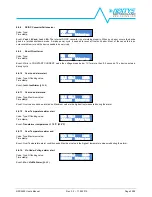
NPS2400
User’s Manual
Rev. 3.0
– 17.02.2015
Page 21/38
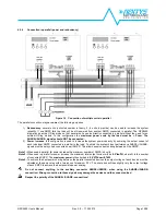
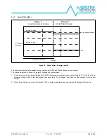
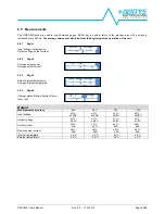
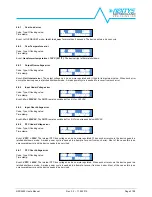
6 User interface
6.1 Principles of operation
An integrated user interface composed of an LCD (alphanumerical, 2 x 16 characters, with backlight), 2 status LEDs and 4
buttons is present on the NPS2400. Through this interface the user can modify, monitor and control the SMPS behaviour.
The physical layout of the interface is shown in Figure 14.
Figure 21 User interface physical layout
MENU KEY
Used to enter and exit various pages in the user menu.
DOWN KEY
Scrolls down menus and values.
UP KEY
Scrolls up menus and values.
OK KEY
Confirms selection
RED
LED
ALARM
Shows an abnormal condition (either external or internal to the SMPS)
GREEN
LED
DC OK /
CHARGE
1. in power supply modes: shows that the device is operating correctly and the output voltage is
regulated
2. in battery charger mode: blinks (1Hz) during charging and turns ON when the battery is charged


