background image

NPSM121 Series Instruction Manual

NPSM121 Series V4.0

www.nextys.com

Page 5/5

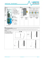
Dismounting:

1.

Pull down the slide clamp lever

2.

Tilt the unit upward

3.

Unhook the unit from the rail

1 & 2

3

Fig.5

Recommended connecting cable

Recommended Tightening torque

0.5-0.6 Nm

4.42-5.30 lbf in

Solid: 2.5mm² / 12AWG

Stranded:1.5mm² / 12AWG

L: 6.0-7.5mm / 0.24-0.30 in

Fig.6

Input protection

Fuse MCB 4A C curve.

For USA and Canada, use the fuse type closest to the European equivalent type.

Surge protection:

it is strongly recommended to provide external surge arresters (SPD) according to local regulations.

Fig.7

Input connections

AC Line

DC Line

Fig.8

Environment

Operating temperature

Derating

- 35°C…70°C

5…95% r.H. non condensing

UL Certified up to 60°C

Overtemperature protection

- 1.2W/°C over 60°C

Note:

Data may change without prior notice in order to improve the product.

Please refer to the latest version of the "Instruction Manual" for each product by visiting

www.nextys.com

See also the products below that can be used in conjunction with NPSM121 units:

(accessory device)

OR20

20A Active ORing controller

OR50

50A Active ORing controller

DCU20

20A High performance DC UPS

BU150U

150J Buffer Module

NUPS12/24

Battery charger and DC UPS Module

MBC2K

2000W Motor brake controller

NBP30

Sealed Lead acid Battery pack

Summary of Contents for NPSM121 Series

Page 1: ...l efficiency Overload 150 Up to 60 C operating temperature with no derating Constant current or Hiccup mode limitation user settable Wide range of output voltage Easy parallelable for power increase Only 35mm width aluminum enclosure INDEX Page Installation Requirements 2 Declaration of Conformity 2 User Instructions 3 Connections 4 Dimensions 4 Distances 4 Mounting 4 Dismounting 5 Input Connectio...

Page 2: ...ispositivo prima di toccarlo Non far entrare liquidi o oggetti estranei nel dispositivo Per evitare scintille non collegare o scollegare l apparecchiatura prima di avere tolto tensione di ingresso e prima che sia avvenuta la scarica dei condensatori interni min 1 minuto RISQUE DE BRULURES EXPLOSION INCENDIE ELECTROCUTION DOMMAGE AUX PERSONNES Ne jamais effectuer des opérations sur les parties sous...

Page 3: ...upply to the load With output voltage set to the max value the continuous current x voltage must not exceed the nominal power 8 Parallel connection and redundancy power supplies can be connected in parallel to increase power For paralleling for power set the Ilim jumper to C C algorithm Uout must be set uniformly 100mV on each power supply and the wiring must be symmetrical to ensure an equal curr...

Page 4: ...gative DC I earth ground Output Positive DC Negative DC Dry contact NC Dimension W D H mm inch 35 1 37 104 4 09 103 4 05 Distance A B mm inch 20 0 8 50 2 0 Fig 4 Mounting Dismounting Instructions For DIN rail fastening according to IEC 60715 TH35 7 5 15 Mounting as shown in figure with input terminals on lower side with suitable cooling and maintaining a proper distance between adjacent devices as...

Page 5: ... SPD according to local regulations Fig 7 Input connections AC Line DC Line Fig 8 Environment Operating temperature Derating 35 C 70 C 5 95 r H non condensing UL Certified up to 60 C Overtemperature protection 1 2W C over 60 C Note Data may change without prior notice in order to improve the product Please refer to the latest version of the Instruction Manual for each product by visiting www nexty...

Reviews: