NUPSxx Series
Instruction Manual
NUPSxx Series V5.0
www.nextys.com
Page 3/5
USER INSTRUCTIONS
1) Description:
DIN rail mountable primary switched-mode power supply with 90...264Vac (110…345Vdc) input, suitable for Single phase main line and DC line.
Functions:
B:
connection to battery PLUS
Battery –:
connection to battery MINUS
PS OK connector:
connection to SPDT contact for operating status/failure remote alarm (P.S. OK signal)
Load +/-:
connection to load PLUS /MINUS
IN +/-:
connection to power supply output PLUS /MINUS
Battery fuse:
protects the battery and its cables against dangerous over currents. 15A Mini car Blade Fuse factory supplied is the max. allowed value, it
can be replaced with a lower value fuse for a better protection with small batteries.
Note:
if the fuse blows and if the module is fed only by the battery and without any voltage connected to IN+, IN– terminals, all LEDs of the
module are turned off.
Charging circuitry:
regulates and controls battery charging current. 2A or 4A charging current can be selected (see Fig.7).
It’s recommended to use 2A with battery capacity up to 20Ah and (if a faster charging time is not required) and 4A current with battery
capacity 20-45Ah max.
PS OK:
green LED, when it lights indicates that power supply is OK and that it is feeding the load and keeping battery under charge too.
PS OK off:
indicates either that the power supply is turned off for AC mains black-out, or is disconnected form the AC mains, or that its output is
overloaded and thus output is turned off for a short circuit - overload, or that the power supply failed.
LOAD OK:
yellow LED, when it lights on indicates that the load receive power, either from the P.S. (PS OK LED On) or from battery (PS OK LED Off).
BATT. OK:
green LED, with the power supply turned off or disconnected indicates that the battery is connected and charged.
Attention:
with the power supply connected and active BATT. OK is always turned on even if the battery is not connected.
BATT. LOW:
red LED, indicates that the battery is charged, increasing current required by the load and/or increasing the battery discharge.
BATT. LOW LED lights on together with BATT OK, and its light intensity can vary depending on current required by the load, or blink if
loads are switched on / off, due to unavoidable battery voltage variations depending on applied load. When BATT. LOW LED is lit, it is
recommended to safely shut down the load, in order to avoid unexpected power loss.
Failure contact:
at 1A/24V SPDT contact switches when the battery starts back-up feed of the load. The remote signal informs that the system is no more
fed by the DC power supply e.g. for a fuse failure or for a power supply failure, thus giving a warning even if there is not a general and
visible black-out but only a local failure.
NUPSxx
restart after a long duration black out with low battery. In such condition the module has disconnected the battery from the load (to prevent total discharge and thus
battery damage). It can be started up only by feeding IN+, IN – with a 24Vdc source (e.g. the power supply or a battery). By connecting only the discharged battery to
BATT. +/- terminals the module cannot be restarted. If the module is feeding the load from the back-up battery and if a short circuit makes the battery protection fuse to
blow, the module can be re-started (after fuse replacement) only by first connecting a 24Vdc power source to IN+,IN – terminals.
2) Installation:
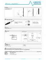
use DIN-rails according to EN60715. Installation should be made vertically (see Fig.4). For better device stability fix the rail to the wall close to the point where
the device is to be mounted. In order to guarantee sufficient convection, we recommend observing a minimum distance to other modules (see Fig.3).
The device is provided with a thermal protection; a limited air flow can cause the thermal protection tripping. The SMPS automatically restarts after cooling.
To get normal operation reduce the temperature of the air surrounding the power supply, increase the ventilation or reduce the load (see Fig.8)
3) Connections
: the device is equipped with pluggable screw terminals. To avoid sparks, do not connect or disconnect the connectors before having previously turned-off input
power and waited for internal capacitors discharge (minimum 1 minute).
In order to comply with UL certification, use appropriate copper cables of indicated cross section, designed for an operating temperatures of:
60°C for ambient up to 45°C
75°C for ambient up to 60°C
90°C for ambient up to 70°C
Strip the connecting ends of the wires according to the indication and ensure that all strands of a stranded wire enter the terminal connection (see Fig.5)
4) Battery protection:
protects the battery and its cables against dangerous over currents. 15A Mini car Blade Fuse factory supplied is the max. allowed value, it can be
replaced with a lower value fuse for a better protection with small batteries (see Fig.6)
5) DC input connection:
connect L terminal to (+) positive pole, N terminal to (-) negative pole and
I
terminal to GND. Rated voltage 110...345Vdc.
The device is also suitable for photovoltaic or wind turbine applications (see Fig.7).
6) Output connection:
The device is suitable for
SELV
and
PELV
circuitry.
Check Uout before connecting the NUPSxx to the load. With output voltage set to the max. value, the continuous current must not exceed the nominal current 10A max.
7) Protection:
the device is protected against
REVERSE battery connection:
a red LED indicates that battery is connected with reversed polarity.
Protection diode:
it avoids the voltage and current supplied by the battery to circulate through the power supply output circuitry and prevents failures due to reverse
polarity connection.
Deep discharge battery protection circuit:
this circuit disconnects the battery when its voltage drops under DDV voltage, to avoid battery damage.
8) GENERAL INFORMATION ON BATTERIES
Rated voltage:
is the voltage that the battery can supply in condition of full charge and rated current. Battery voltage without load is always higher of rated voltage.
Capacity:
given in Ah (Ampere / hour) measured at 25°C/ 77°F. (e.g. at 10Ah battery can supply 10A for 1 hour or 1A for 10 hours).
Charging current:
is the current to be applied to charge the battery, usually indicated by the manufacturer. A charging current higher than specified can damage the battery or
shorten its life, a too low charging current results in a too long charging time and uncompleted or partial charge, thus reduced Ah capacity.
Charging current of sealed lead batteries would never exceed 20% of capacity of the battery. The battery limits by itself the charging current supplied by the battery charger,
depending on its charge status. Only when the battery is completely discharged it’s possible to apply the maximum charging current.
Note:
when choosing the capacity of the battery, consider that real capacity indicated by manufacturers can vary compared with rated capacity depending quality and cost,
capacity is always given for new battery at 25°C/77°F, but during battery life it’s capacity decreases due to ageing, even if the battery is not used, so calculate battery capacity
and duration considering the worst operating conditions.
Discharge voltage:
the right charging voltage value is given by the manufacturer; generally the voltage/current source must be capable to supply a voltage 10-15% higher than
rated voltage of the battery. If charging voltage is lower than +10% of battery rated voltage, charging time increases and produce an uncompleted charge and thus a reduced
capacity. Charging voltages higher than +20% of rated voltage can damage the battery and shortens its life.
Charging time:
varies according to charging current/voltage. Consider a minimum charging time of 3-4 hours after a battery discharge.
Discharged battery:
a battery is considered discharged when its voltage, measured applying a 50% load, is lower than -10% of rated voltage, or when voltage measured with
no load is lower than rated voltage.
Total discharge:
when a battery gives a voltage between 0 - 60% of rated voltage, it’s totally discharged. Total or deep discharge reduces battery life and must be avoided.
Disconnect the battery from the load when voltage is lower than e.g. 18V/9V in at 24V/12V battery.
Operating temperature:
for a long duration of the battery operating temperature must be kept within 10°C/+50°F…30°C/+ 86°F. Battery duration decreases outside this
range. At low temperatures the battery might not supply rated Ah, because electrochemical reaction are less efficient.
Overload–short circuit battery protection:
battery and its connecting cables must be protected with overcurrent protection devices (fuses, circuit breakers, etc.) able to cut-
off dangerous currents.


