background image

NUPSxx Series

Instruction Manual

NUPSxx Series V5.0

www.nextys.com

Page 4/5

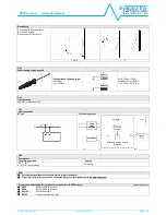
Fig.1

Connections

Fig.2

Dimensions

Fig.3

Distances

Just for reference

(1)

DC input

(2)

DC output (load)

(3)

Battery connection

(4)

Diagnostic Output dry contact

NC Power Supply OK

(5)

Green LED: Power Supply OK

(6)

Yellow LED: Load OK

(7)

Charging current jumper

(8)

Green LED: Battery OK

(9)

Red LED: Battery Low

(10)

Red LED: Batt. Reverse polarity

Input DC Line:

IN + = + Positive DC

IN - = - Negative DC

Output:

LOAD + = Positive Load

LOAD - = Negative Load

BATT + = Positive DC Battery

BATT - = Negative DC Battery

Dry contact = NC

Dry contact = NO

Dimension

W

D

H

mm (inc)

54.0 (2.16)

110.0 (4.33)

115.0 (4.52)

Distance

A

B

mm (inch)

20 (0.8)

50 (2.0)

Fig.4

Mounting / Dismounting Instructions

For DIN rail fastening according to IEC 60715 TH35-7.5(-15)

Mounting as shown in figure, with input terminals on lower side, with suitable cooling and maintaining a proper distance between adjacent devices as specified in the I.S.

manual of each family.

Mounting:

1

2

1.

Tilt the unit slightly backwards.

2.

Fit the unit over the top edge of the rail.

3.

Slide it downward until it hits the stop.

4.

Press against the bottom for locking.

3

4

Summary of Contents for NUPS12

Page 1: ... for power supplies with adjustable output To be used with Lead acid batteries ONLY Allows to feed the load and to charge the battery at once Built in battery protection fuse Low battery cut off system INDEX Page Installation Requirements 2 Declaration of Conformity 2 User Instructions 3 Connections 4 Dimensions 4 Distances 4 Mounting 4 Dismounting 5 Input Connections 5 Environment 5 Accessory Dev...

Page 2: ...te RISCHIO USTIONI ESPLOSIONE INCENDIO SCOSSA LESIONI GRAVI Non effettuare mai operazioni sulle parti sotto tensione Pericolo di lesioni letali Il contenitore può scottare lasciar quindi raffreddare il dispositivo prima di toccarlo Non far entrare liquidi o oggetti estranei nel dispositivo Per evitare scintille non collegare o scollegare l apparecchiatura prima di avere tolto tensione di ingresso ...

Page 3: ... minute In order to comply with UL certification use appropriate copper cables of indicated cross section designed for an operating temperatures of 60 C for ambient up to 45 C 75 C for ambient up to 60 C 90 C for ambient up to 70 C Strip the connecting ends of the wires according to the indication and ensure that all strands of a stranded wire enter the terminal connection see Fig 5 4 Battery prot...

Page 4: ...ve Load LOAD Negative Load BATT Positive DC Battery BATT Negative DC Battery Dry contact NC Dry contact NO Dimension W D H mm inc 54 0 2 16 110 0 4 33 115 0 4 52 Distance A B mm inch 20 0 8 50 2 0 Fig 4 Mounting Dismounting Instructions For DIN rail fastening according to IEC 60715 TH35 7 5 15 Mounting as shown in figure with input terminals on lower side with suitable cooling and maintaining a pr...

Page 5: ...i Car blade fuses 15A Fig 7 Input connections DC Line Schematic connection Fig 8 Environment Operating temperature Derating 40 C 50 C 5 95 r H non condensing No derating Note Data may change without prior notice in order to improve the product Please refer to the latest version of the Instruction Manual for each product by visiting www nextys com See also the products below that can be used in con...

Reviews: