PSH150
user manual rev4
Page 8/15
3.2 Auxiliary 12V output
PSH150 is provided with an auxiliary regulated 12V output with up to 100mA current capacity. This
output is short circuit protected. The auxiliary output shares the same ground (negative terminal) with
the main DC output.
3.3 INHIBIT input
An
opto-isolated
input allows switching off the main DC output. The polarity of the input can be
defined using the
“inhibit polarity” (POL)
field (§3.4.2). The controlling signal must have a voltage
between 5Vdc and 30Vdc. The auxiliary 12V output is always active and can not been switched off.
3.4 Display interface
The PSH150 is provided with a 3-digits 7-segments LED display used to indicate the status and to
navigate through the configuration menus. During normal operation, the output parameters are
reported (§3.4.1). Alarms and error codes are also reported on the display (§3.4.3)
3.4.1 Normal operation
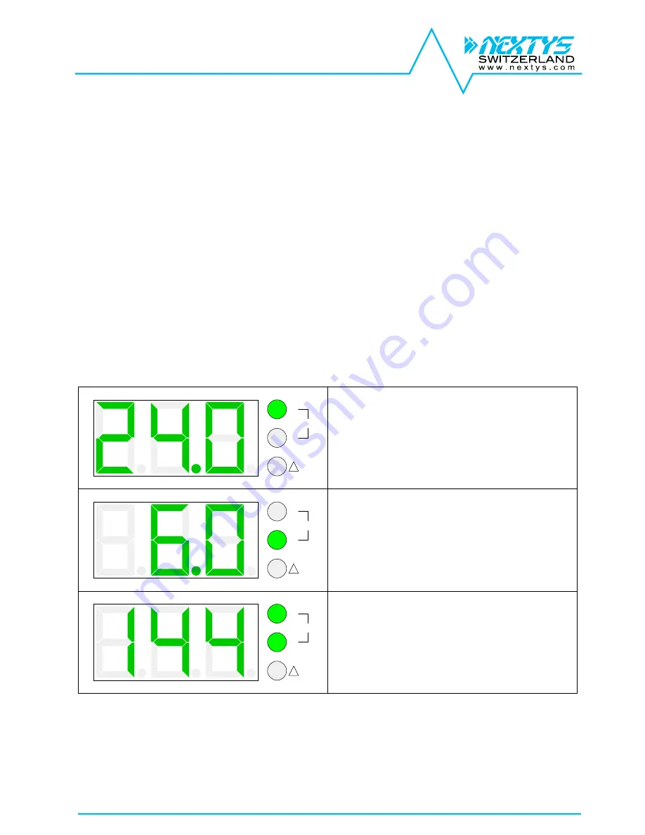
During normal operation the output voltage, current and power are reported on the display. 2 green
LEDs indicate which measurement is currently shown. Every parameter is visible for 3 seconds, then
the next measurement is shown.
V
A
!
W
Output voltage measurement:
The display is indicating 24.0V. Note that the
“V”
green LED is on, indicating voltage
measurement.
V
A
!
W
Output current measurement:
The display is indicating 6.0A. Note that the
“A”
green LED is on, indicating current
measurement.
V
A
!
W
Output power measurement:
The display is indicating 144W. Note that both
the
“V” and “A”
green LEDs are on, indicating
power measurement.
.


