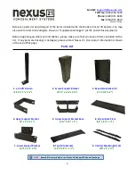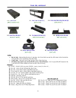
11
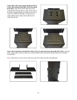
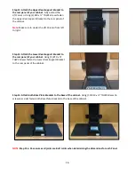
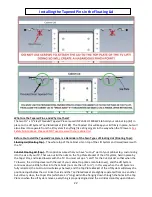
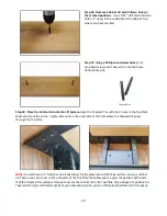
Step 6: Fasten the
Screen Support Bracket
(Part # 2)
and the
Rear Panel Bracket
(Part # 13) to the
Swivel
Mechanism.
Align the four threaded holes on the
Swivel Mechanism
with the four outer most holes on
the
Screen Support Bracket
and the four outer most
holes on the
Rear Panel Bracket.
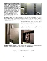
Using (4)
6mm x
12mm BHMS Screws
attach both brackets to the
Swivel Mechanism.
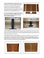
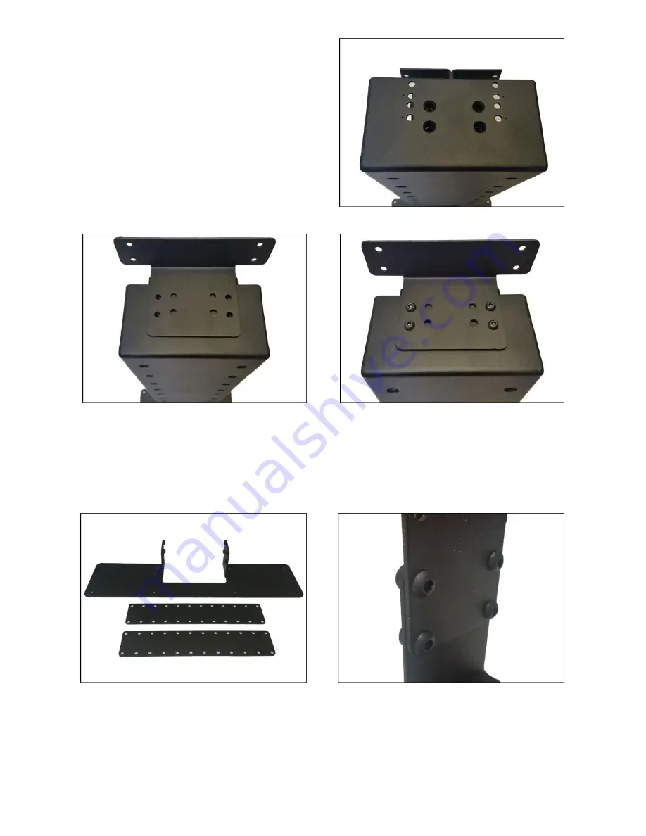
Step 7: Attach the
Bottom Panel Bracket
(Part # 15) to the
Accessory Mounting Brackets
(Part #12).
Using
(8)
6mm x 10mm BHMS Screws
(4 screws per bracket) fasten both
Accessory Mounting Brackets
to the
Bottom
Panel Bracket
.
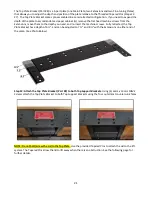
NOTE:
Make sure you use the lower most four holes on the
Accessory Mounting Brackets.
Summary of Contents for L-45ens
Page 1: ...TV Lift System Model L 45ens Installation Instructions ...
Page 2: ...2 ...
Page 27: ...27 Supplemental Page A L 45ens Installation Dimensions ...
Page 28: ...28 Supplemental Page A L 45ens Installation Dimensions Page 2 ...
Page 30: ...30 Supplemental Page C Connect the Lift to Home Control System ...
Page 31: ...31 ...
Page 32: ...32 866 500 5438 ...


