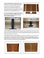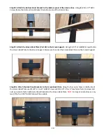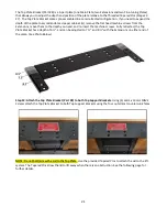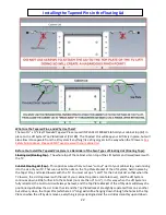
26
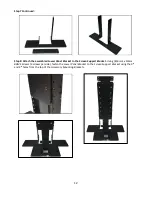
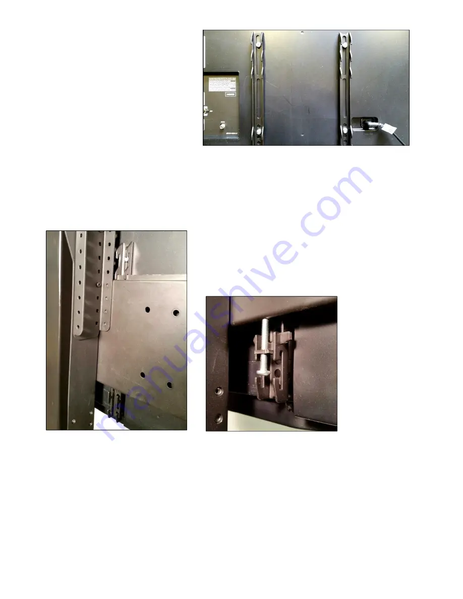
Step 29: Attach the
Vertical Mounting Bars
(Part #9) to the TV.
Before you begin, hand
thread screws (found in bag labeled “TV
Mounting Screws/Spacers”) into the threaded
inserts on the back of your TV to determine
the correct screw diameter (M6 or M8). The
length of the screw required will depend on
whether the TV has a flat/unobstructed or
irregular/obstructed back. Follow diagram
“A”
for TV’s with flat/unobstructed back.
Use diagram
“B”
for TV’s with irregular/
obstructed back. The diagrams can be
found on the previous page.
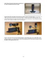
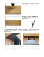
Step 30: Mount the TV (with the
Vertical Mounting Bars
attached) to the
Screen Back Plate
.
Each
Vertical
Mounting Bar
has “hooks” on either end that allow the bars to “hang” on the Screen Back Plate. Lift the TV
onto the
Screen Back Plate
. Center the TV. Be sure that both the upper and lower set of “hooks” fully engages
with the
Screen Back Plate.
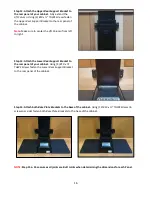
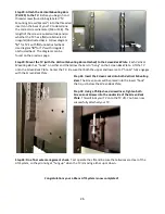
Step 31: Insert the
Screen Locks
into both
Vertical Mounting
Bars
.
The
Screen Locks
will be placed into the lower “hook”
that is just below the
Screen Back Plate
.
Step 32: Using a Phillips head screwdriver, tighten both
Screen Lock Screws
into the underside of the
Screen Back
Plate
.
This will lock your TV onto the TV Lift. You have now
successfully attached your TV.
Step 33: Do a final wire management check.
Test operate the Lift and be sure that all wires are clear of the
Lift System, so they do not get “hung up” when the TV is moving either up or down.
Congratulations your L-45ens Lift System is now completed!
Summary of Contents for L-45ens
Page 1: ...TV Lift System Model L 45ens Installation Instructions ...
Page 2: ...2 ...
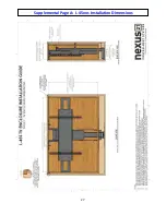
Page 27: ...27 Supplemental Page A L 45ens Installation Dimensions ...
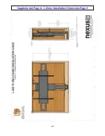
Page 28: ...28 Supplemental Page A L 45ens Installation Dimensions Page 2 ...
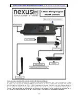
Page 30: ...30 Supplemental Page C Connect the Lift to Home Control System ...
Page 31: ...31 ...
Page 32: ...32 866 500 5438 ...

