e
Electro Industries/GaugeTech
Doc # E134-7-15 V1.01
12-4
4,294,967,296 / 0.
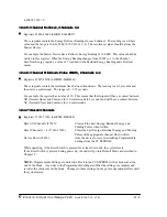
12.4.5: Channel Rollover, Channels 1-4
12.4.5: Channel Rollover, Channels 1-4
n
Registers 45081-45096 (0x0B018-0x0B027)
These registers contain the Energy Rollover Readings for each channel. The reading is an 8-byte
value and the range is 18,446,744,073,709,551,615 / 0. These rollover values should be from the
Master Device.
For example, the Master Device has a Rollover Energy Reading of 100,000. This value should be
written in this register. When the Energy Reading changes from 99,992 to 1 in the Channel
Last/Next Energy register, a value of 9 is added to the Residual Energy Reading and a Rollover
occurs.
12.4.6: Channel Minimum Pulse Width, Channels 1-4
12.4.6: Channel Minimum Pulse Width, Channels 1-4
n
Registers 45097-45100 (0x0B028-0x0B02B)
These registers contain the minimum time between transitions. The reading is a 2-byte value and
the unit is a centisecond. The range is 0 - 2.55 seconds.
For example, the register has a value of 10. This means that the Output will have a contact between
NO (Normal Open) and Common for 10 centiseconds (0.1 second) and will have a contact between
NC (Normal Close) and Common for 10 centiseconds.
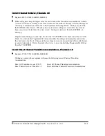
12.4.7: Reset Channels
12.4.7: Reset Channels
n
Registers 57345-57349 (0x0E000-0x0E004)
Reset All Channels (57345):
Clears all the Last Energy, Residual Energy and
Pending Pulses when written.
Reset Channels 1 - 4 (57346-57349):
Clears the Last Energy, Residual Energy and Pending
Pulses of the appropriate channel when written.
Device Reset (65410):
Asks the device to reset, reinitializing Programmable
Settings from the I
2
C EEPROM.
While operating, if the Reset Switch is pressed for at least 2 seconds, the system resets.
If the Reset Switch is pressed during power up, the unit will go into Default Mode as described in
Chapter 5.
NOTE:
Programmable Settings are stored in a block in the I
2
C EEPROM with a checksum at the
end of the block. Any write to the Programmable Settings modifies the settings, recomputes and
rewrites the checksum on the block. Changes to these settings do not go into operational effect until
the system resets.
Summary of Contents for I/O Module
Page 2: ......
Page 6: ...e Electro Industries Gauge Tech Doc E134 7 15 V1 01 iv ...
Page 10: ...e Electro Industries Gauge Tech Doc E134 7 15 V1 01 viii ...
Page 30: ...e Electro Industries GaugeTech Doc E134 7 15 V1 01 2 16 ...
Page 44: ...e Electro Industries GaugeTech Doc E134 7 15 V1 01 4 8 ...
Page 50: ...e Electro Industries GaugeTech Doc E134 7 15 V1 01 6 4 ...
Page 52: ...e Electro Industries Gauge Tech Doc E 134 7 15 V1 01 7 2 ...
Page 63: ...e Electro Industries GaugeTech Doc E134 7 15 V1 01 8 4 ...
Page 65: ...e Electro Industries Gauge Tech Doc E 134 7 15 V1 01 9 2 ...
Page 72: ...e Electro Industries GaugeTech Doc E134 7 15 V1 01 10 4 ...
Page 74: ...e Electro Industries Gauge Tech Doc E 134 7 15 V1 01 11 2 ...
Page 81: ...e Electro Industries Gauge Tech Doc E 134 7 15 V1 01 13 2 ...
Page 87: ...e Electro Industries GaugeTech Doc E134 7 15 V1 01 14 4 ...
Page 89: ...e Electro Industries Gauge Tech Doc E 134 7 15 V1 01 15 2 ...


