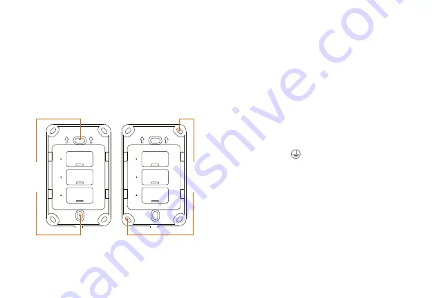
There are two mounting methods:
Screws can be inserted
at the center or on the sides of the switch, as shown in the
image below.
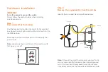
- Using the correct polarity, match each terminal on the
smart switch with the wires coming from the electrical
box, as shown in the diagrams.
- Attach the wire end to the terminal screw and tighten
until it is fully secured. Repeat this step for each cable.
Note:
Follow the wiring configuration below when making
hardware connections:
1) Neutral wire (white) on the electrical box to the neutral
terminal (N) on the smart switch.
2) Ground wire (yellow/green) on the electrical box to the
ground terminal on the smart switch (ground wire
maybe yellow/green or bare copper wire) depending on
existing electrical installation.
3) Line/Live wire (black) on the electrical box to the to line
/live terminal on the smart switch.
4) Load wire (red) on the electrical box to each load
terminal (L1, L2 y L3) on the smart switch.
Mounting
method 1
Mounting
method 2
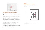
Step 4
Mount the smart switch


