background image


 DP060LM/DP120LM/DP180LM 

247

11. Specifications 


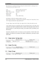
11.1


Output phase Configuration ······························ 248


11.2


Output Function ············································· 248


11.3


Output Range ················································ 248


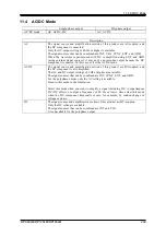
11.4


AC/DC Mode ················································· 249


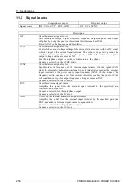
11.5


Signal Source ················································ 250


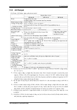
11.6


AC Output ···················································· 251


11.7


DC Output ···················································· 253


11.8


Output Voltage Stability ··································· 254


11.9


Distortion of Output Voltage Waveform ··············· 255


11.10


Power Input ·················································· 255


11.11


Withstand Voltage and Insulation Resistance ······· 255


11.12


Measurement Function ···································· 255


11.13


Power Unit Energization Setting ························ 259


11.14


Current Limiter ·············································· 260


11.15


Setting Range Limit Function ····························  262


11.16


Remote sensing ············································· 263


11.17


AGC ····························································  264


11.18


Autocal ························································ 265


11.19


Sequence ·····················································  266


11.20


Simulation ···················································· 267


11.21


Clipped Sine Wave ········································· 268


11.22


Arbitrary Wave ··············································· 268


11.23


External Signal Input ······································· 269


11.24


General Function ··········································· 270


11.25


Memory Function ··········································· 271


11.26


Self-diagnosis/Protection Function ····················· 272


11.27


External Control Function ································ 272


11.28


External Interface ··········································· 274


11.29


USB Memory Interface ···································· 275


11.30


Waveform Monitor Output ································ 276


11.31


EMC ····························································  277


11.32


Operation Environment ··································· 277


11.33


Externals, Weight, and Terminal Block ················ 278


11.34


Option ························································· 278


11.35


Outline Dimensional Drawing ···························· 280


Summary of Contents for DP060LM

Page 1: ...PROGRAMMABLE AC POWER SOURCE DP060LM DP120LM DP180LM INSTRUCTION MANUAL NF Corporation...

Page 2: ......

Page 3: ...PROGRAMMABLE AC POWER SOURCE DP060LM DP120LM DP180LM INSTRUCTION MANUAL DA00059920 004...

Page 4: ......

Page 5: ...f this product 2 Preparation before Use Explains the preparations carried out before installation or operation 3 Basic operation Explains the component names and basic operations 4 Advanced Operation...

Page 6: ...ive grounding conductor is connected before you connect a cable to the power input terminals L L1 L2 L3 and N For grounding use a power cable of sufficient ampacity for the maximum current consumption...

Page 7: ...ning occurs power off this product and cut the power at the distribution board A lightning may cause an electric shock a fire and a failure Safety symbols The following shows the general definitions o...

Page 8: ...ssis Request about disposal For environmental preservation pay attention to the followings when you dispose of this product a Do not discard this product in domestic household waste This product shall...

Page 9: ...output 20 2 6 How to Tilt Control Panel 21 2 7 Simple Operation Check 23 2 8 Calibration 26 3 Basic Operation 27 3 1 Component Name 28 3 1 1 Front 28 3 1 2 Rear 29 3 1 3 Control panel 31 3 2 Power On...

Page 10: ...3 4 13 Clearing the Output Current Peak hold Value 59 3 4 14 Switching the Target Phase of which the Measured Values are Displayed Polyphase Output 61 4 Advanced Operation 63 4 1 Using Limiter Settin...

Page 11: ...3 Measurement Method 131 4 5 4 Measurement Tips 132 4 6 Using Clipped Sine Wave 132 4 7 Outputting Arbitrary Waveform 135 4 7 1 Basics 135 4 7 2 Arbitrary Waveform Creation Procedure 136 4 7 3 Arbitr...

Page 12: ...efault Setting Reset 194 5 Description of Screen and Menu 197 5 1 Screen Configuration 198 5 1 1 Status Icon 199 5 1 2 Measured Value Display Items 200 5 1 3 Output Setting Display Items 201 5 1 4 War...

Page 13: ...tenance 241 10 1 Preface 242 10 2 Daily Maintenance 242 10 3 Storage Repackaging Transportation 244 10 4 Checking Firmware Version 244 11 Specifications 247 11 1 Output phase Configuration 248 11 2 Ou...

Page 14: ...270 11 25 Memory Function 271 11 26 Self diagnosis Protection Function 272 11 27 External Control Function 272 11 27 1 CONTROL I O 273 11 27 2 Control of Peripherals by Device Control 274 11 28 Extern...

Page 15: ...Edit View 100 Figure 4 8 Sequence Control View Output Off State 100 Figure 4 9 Sequence Control View Output On State Sequence in Execution 100 Figure 4 10 Sequence Control View Output On State Sequen...

Page 16: ...r Filters 219 Figure 8 1 The Control Cable Connection Diagram of DP060LM and DP4162 RIN in Single phase Output 225 Figure 8 2 The Control Cable Connection Diagram of DP060LM and DP4173 DP4172 DIP in T...

Page 17: ...Values of the Output Voltage and Output Current 55 Table 4 1 Wattage Limiter Value per Phase Reference value 71 Table 4 2 Parameters of Sequence Function 74 Table 4 3 Example of Editing Sequence 77 Ta...

Page 18: ...f the Sequence Function 203 Table 5 7 Menus of the Simulation Function 204 Table 5 8 Menus of the Memory Function 204 Table 5 9 System Menus 205 Table 7 1 Fixing Bracket Model Names 218 Table 7 2 Repl...

Page 19: ...DP060LM DP120LM DP180LM 1 1 Outline 1 1 Overview 2 1 2 Series Lineup 2 1 3 Features 3...

Page 20: ...this manual Also it is to be noted that DC regeneration is described as sink current and DC power running is described as source current 1 2 Series Lineup This product operates single phase model or...

Page 21: ...n test Simulation function User can simulate power line abnormalities such as blackout voltage rise voltage drop abrupt phase change abrupt frequency change and so on Variable current limiter This fun...

Page 22: ...owing data to from a commercial USB memory stick Basic setting Sequence Simulation Arbitrary waveform Restriction of power usage during operation The efficiency is improved by about 27 compared to the...

Page 23: ...ng with IEC 61000 4 11 can be performed In addition Large capacity model is also available for IEC 61000 4 34 test In this document it is written as DIP When using this product in combination with DIP...

Page 24: ......

Page 25: ...heck before Use 8 2 2 About Installation Environment 9 2 3 Cautions during Moving and Transportation 12 2 4 Grounding and Power Connections 13 2 5 Output Cable Connection 17 2 6 How to Tilt Control Pa...

Page 26: ...the LCD screen keys jog or shuttle of the control panel or rear connectors Contents main unit and accessories check The contents are listed in Table 2 1 Make sure that all of the main unit and accesso...

Page 27: ...00 kcal h DP180LM 18 kVA 5 4 kW 4650 kcal h Note Estimate at power input single phase 200 V or three phase three wire 200 V or three phase four wire 380 V phase voltage 220 V rated output Install the...

Page 28: ...PROGRAMMABLE AC POWER SOURCE 10 Refer to Figure 2 1 Assembly Diagram of Stabilizer and assemble the stabilizer of accessories of DP120LM because it is necessary to ensure stability Figure 2 2 Assembl...

Page 29: ...g m3 without condensation However on some specifications the temperature range limit is more strict Do not install the product in the following places Place exposed to inflammable gas This may pose a...

Page 30: ...ntal surface To move the product on a sloped or uneven surface a licensed personnel should move it by operating a lifting machine or crane instead of the casters As this product is heavy whenever it i...

Page 31: ...be taken from the distribution board Be sure to switch off the breaker at the distribution board before connecting this product to the distribution board Otherwise an electric shock might occur Route...

Page 32: ...2 4 Power Input Terminal Power input DP060LM DP120LM DP180LM Screw 1P2W M6 M8 3P3W M10 3P4W M6 Note The power input 1P2W is not selectable for DP180LM About power cable Use a cable of sufficient ampa...

Page 33: ...terminal cover so that the cables pass through the cutout 4 Ensure that the power switch of this product is turned off and then connect the power cable to the distribution board Be sure to check phas...

Page 34: ...L2 L3 N Distribution board L1 L2 L3 Distribution board Protective grounding Power input three phase three wire Power input three phase four wire Power input and output panel DP060LM DP120LM Power inp...

Page 35: ...is used in single phase two wire output 1P2W Polyphase output terminal is used in single phase three wire output 1P3W and three phase four wire 3P4W Table 2 6 shows the screw sizes of the output term...

Page 36: ...ngle phase output Connection procedure 1 Remove the resin molded cover of power input and output panel in case DP060LM DP120LM or that of output panel in case DP180LM Also remove the single phase outp...

Page 37: ...tach the resin molded terminal cover so that the cutout of the cover faces upside Do not remove the polyphase output terminal cover Attach the polyphase output terminal cover so that the cutout of the...

Page 38: ...rrent exceeding the maximum current per phase see 11 6 and 11 7 to any output terminal including N terminal 3 Attach the resin molded cover of polyphase output panel in case DP060LM DP120LM or that of...

Page 39: ...chassis being pulled by a spring The hook consists of two steps which can be used to tilt the control panel and fix it in two ways DP060LM Polyphase output panel cover Power input and output panel cov...

Page 40: ...you and the lock of the control panel is released 2 While holding the lever in pulled position tilt the control panel by desired degree 3 Release the lever slowly The control panel will be locked Whe...

Page 41: ...ent Operation procedure 1 Connect the product to the mains referring to 2 4 Grounding and Power Connections 2 Attach the resin molded output terminal cover and the output cable holder without connecti...

Page 42: ...uct refer to 4 27 Restoring to the Factory Default Setting Reset to initialize the product to factory defaults The product will be reset and display the Continuous screen automatically 6 When you purc...

Page 43: ...on is displayed for the three phase output and check that the icon is displayed for the single phase three wire output Press the Osc soft key and select 6 Phs Mode to display the Phase Mode window and...

Page 44: ...PUT key to turn the output on Press the V key to open the numerical entry box for AC voltage ACV Raise the AC voltage setting value gradually by using the jog shuttle arrow keys and numeric keypad 2 8...

Page 45: ...DP060LM DP120LM DP180LM 27 3 Basic Operation 3 1 Component Name 28 3 2 Power On Off 32 3 3 Basic Key Operations 35 3 4 Using the Continuous Function 41...

Page 46: ...he settings and turns the output on or off Information such as setting values and measured values is displayed on the LCD screen 3 1 3 3 Remote controller connector Optional remote controller can be c...

Page 47: ...ick change sync output connector 16 CONTROL SIGNAL connector 17 CONTROL IN connector 8 Air outlet 9 Power input terminal 12 Sensing input terminal 13 Resin molded cover 11 Single phase output terminal...

Page 48: ...W either of which can be chosen when ordering The power input 1P2W is not selectable for DP180LM Figure 3 2 shows the case of power input 3P3W 2 4 10 Polyphase output terminal Output terminal for the...

Page 49: ...4 OUTPUT key Turns the output on or off 3 4 9 5 RANGE key Switches between the 100 V and 200 V ranges 3 4 3 6 MENU key Displays the root menu 3 3 1 7 Soft key Assigned with the functions displayed at...

Page 50: ...CANCEL key Returns to the previous state without confirming the selection The numerical entry box is closed when the value was incremented or decremented using the jog shuttle or arrow key 3 3 3 2 Pow...

Page 51: ...shown in the figure below Check the self check result and press the ENTER key to resume the startup process 3 Depending on the output function selection setting at power on the Continuous function sc...

Page 52: ...ow The value in the icon indicates the maximum electric power that can be output In this case the maximum electric power is 6 0 kVA If the rated power is restricted by the power unit energization sett...

Page 53: ...n upper line represents the Continuous function Sequence function and Simulation function from the left When you press the ENTER key the screen for the selected function is displayed You cannot change...

Page 54: ...items in a selection box which are different depending on setting Data list box When selecting data in the memory the data list box shown in the screen below is displayed To select a data in a data l...

Page 55: ...with the OK Cancel button Following three methods are available to close the window with the OK button or Cancel button shown in the figure below Move the cursor to the OK button or Cancel button in...

Page 56: ...the numerical entry box is closed Enter values directly by using the numeric keypad For an item required to set values hover the cursor over a value which will be highlighted and enter a new value by...

Page 57: ...is changed in a way shown in Table 3 5 When you press a key in the numeric keypad the corresponding value or symbol is entered To move the cursor position use the right or left arrow key When you pre...

Page 58: ...in the following order L1 L2 L3 unbalanced mode All Phase and All Line balanced mode 3 4 6 4 15 M L1 L2 L3 Switches the target phase of which the measured value is displayed in the following order L1...

Page 59: ...witching See 4 8 1 Operation procedures 1 Press the MENU key to move to the root menu in the Continuous function and then select System The system setting window opens Notes Move to the root menu in t...

Page 60: ...ire 1P2W output do not connect anything to the polyphase output terminal In the single phase three wire 1P3W output and the three phase four wire 3P4W output do not connect anything to the single phas...

Page 61: ...signal source and the amplification section and both of the AC component and the DC component are output DC Only the DC voltage can be set the AC voltage is fixed to zero The DC coupling is used betw...

Page 62: ...INT AC VCA AC SYNC AC EXT AC ADD ACDC ACDC INT ACDC SYNC ACDC EXT ACDC ADD DC DC INT DC VCA 1P3W AC AC INT AC VCA AC SYNC ACDC 1 ACDC INT ACDC SYNC DC 3P4W AC AC INT AC VCA AC SYNC ACDC 1 ACDC INT AC...

Page 63: ...al source Operation procedures by using shortcuts 1 Switching the AC DC mode Press the SHIFT key to enter the shift state the SHIFT LED illuminates When you press the 7 key of the numeric keypad durin...

Page 64: ...r 200 V range Table 3 10 shows the setting range for each range Notes You cannot switch the output range in the output on state Table 3 10 The Setting Range per Output Range Setting Item Setting Range...

Page 65: ...ge Operation procedures using the RANGE key The range is toggled between 100 V range and 200 V range every time you press the RANGE key 3 4 4 Setting Waveforms You can select a waveform of the interna...

Page 66: ...etting ACV is also switched as described above if you switch the waveform selection between SIN CLP and ARB Set ACVs for SIN CLP and ARB in the output off state before you change the waveform in the o...

Page 67: ...he output voltage in the ACV item For the DC component set it in the DCV item Notes The output voltage setting is common between SIN and CLP but ARB is independent of these When you switch the wavefor...

Page 68: ...e operations in the balanced mode in a polyphase output In the balanced mode the phase voltage and the line voltage are set for all phases at once To enter the balanced mode select the Osc soft key 6...

Page 69: ...tage 1 Press the Osc soft key and select 5 Target Phs 5 All Line Or perform the Shortcut operation to switch to All Line Check that the icon in the output display area see 5 1 is single phase three wi...

Page 70: ...ff Phase Set the phases when the output turns on off After the output on operation the voltage output is started from the output on phase After the output off operation the voltage output is completed...

Page 71: ...the off phase select Disable 3 Close the window For how to close the window see 3 3 4 Notes The output on off phase setting is invalid for the Sequence and the Simulation 3 4 9 Turning the Output On o...

Page 72: ...ent A Imax Output current maximum peak value The maximum peak value of the output current When the line voltage display is L1 L2 L2 L3 L3 L1 the phase current of the L1 L2 L3 phase is displayed respec...

Page 73: ...cy The measured frequency value of the synchronization signal source when the signal source is SYNC Hz 3 4 11 Switching the Display Format RMS AVG Peak of the Measured Value You can switch the display...

Page 74: ...Operation procedures by using shortcuts 1 Switching the display format of the measured values Press the SHIFT key to enter the shift state the SHIFT LED illuminates When you press the 3 key of the nu...

Page 75: ...play mode is changed to RMS AVG from Peak the effective average values are displayed instead of the maximum and minimum peak values If the AC DC mode and the signal source are changed in the Simple Vi...

Page 76: ...played in the Simple View mode procedure 1 1 In the Simple View mode press the Measure soft key and select 4 Disp Item The setting window for display items opens 2 In the Item1 to Item3 items select m...

Page 77: ...s 3 4 13 Clearing the Output Current Peak hold Value The output current peak hold value is the maximum absolute value of the measured output current peak value which is then updated appending signs an...

Page 78: ...ey 3 Close the window For how to close the window see 3 3 4 Operation procedures by using shortcuts 1 Clearing the current peak hold value Press the SHIFT key to enter the shift state the SHIFT LED il...

Page 79: ...ltage display RMS display is not the line voltage value that is measured directly This is the value that is calculated based on the phase setting value and the measured phase voltage value In the line...

Page 80: ...window see 3 3 4 Operation procedures by using shortcuts 1 Switches the target phase of which the measured value is displayed Press the SHIFT key to enter the shift state the SHIFT LED illuminates Wh...

Page 81: ...Function 164 4 14 Adjusting DC Offset 168 4 15 Using for Unbalanced Polyphase Output 169 4 16 Using as DC Power Supply 171 4 17 Setting Voltage using External DC Input Signal 173 4 18 Control Using E...

Page 82: ...imiter Overvoltage protection may be avoided by lowering the limiter setting value both for negative and positive values When the number of power units that are energized is increased or decreased bas...

Page 83: ...elect 1 Ipk Limiter or push Opens the peak current limiter set window 2 In the Iop Iop item set the peak current limiter value of positive negative 3 Set the Output OFF item as Enable or Disable When...

Page 84: ...quickly For peak current limiter see 4 1 1 RMS current limiter may not be able to limit output current sufficiently if the load impedance is very small e g output short circuit Also RMS current prote...

Page 85: ...ft key to select 2 Irms Limiter or push I key Opens the RMS current limiter set window 2 Set the value of RMS current limiter in Io item 3 Set the Output OFF item as Enable or Disable When setting to...

Page 86: ...e limiting value should be set using the effective value or the positive and negative peak value The effective value can be used only when in the AC mode and the waveform is a sine wave or a clipped s...

Page 87: ...ak value setting 3 Close the window 4 1 4 Using Frequency Setting Range Limit You can limit the range of the frequency setting value for the internal signal source by using the frequency setting range...

Page 88: ...t the upper value of the frequency setting range limit is higher than or equal to the lower limit 3 Close the window 4 1 5 About Wattage Limiter The wattage limiter operates when trying to output the...

Page 89: ...power unit VA may exceed the rated power depending on the power factor of the load Set the output voltage so that the apparent power does not exceed the rated power regardless of the operation of the...

Page 90: ...flow between two or more steps This defines duration of each step and the next step to transition Settings of step synchronous code and trigger output are included in step control parameter for conve...

Page 91: ...tus of the previous step Previous step Next step Previous step Next step Previous step Next step Used as the setting value in the next step Keeps the final value of the previous step Changes from the...

Page 92: ...Phase Stop Phase Trigger output Frequency Waveform Phase angle AC phase voltage DC voltage Frequency Freq waveform Wave phase angle Phase AC phase voltage ACV DC voltage DCV The setting for the outpu...

Page 93: ...sitions to step No 0 and enter into the stand by state When Hold is selected the output at the end of the step is suspended and the execution transitions to the step of the next number when Resume ins...

Page 94: ...set and then transitions to the next step As the result the actual step time is longer by one cycle at a maximum than the set Step Time Figure 4 3 shows an example where both the Stop Phase of the pre...

Page 95: ...CV 0 V 100 V Optional 50 V Step Behavior Sweep Sweep Keep Const Notes Step Time and the Step Behavior of step No 0 specifies the action after the transition to step No 0 at the end of a sequence Jump...

Page 96: ...tput state is kept until the step reaches the specified Stop Phase If Jump to setting is on transitions to the specified step for the specified times Transitions to the step of the next number or step...

Page 97: ...ted contents of sequence save them in the Sequence Memory see 4 2 8 When the sequence is loaded from Sequence Memory the sequence being edited at that time is discarded You can also turn the output on...

Page 98: ...Edit a sequence 1 Push Osc soft key on Sequence Edit View then select AC DC mode and 100 V 200 V range To edit the saved sequence load the sequence see 4 2 6 2 Set the parameter of each step You can m...

Page 99: ...Function DP060LM DP120LM DP180LM 81 3 You can select s or ms as the unit of Step Time by selecting Misc soft key 1 TimeUnit 4 You can set polarity of trigger output and pulse width by selecting Misc s...

Page 100: ...equence is loaded the sequence being edited at that time is discarded In Sequence Control View a sequence cannot be loaded Load the sequence stored in the internal memory 1 In Sequence Edit View selec...

Page 101: ...LM DP180LM 83 3 Specify the memory number of the sequence to be loaded in Memory No item and then push Recall soft key 4 The confirmation window for loading the sequence opens Select OK The sequence w...

Page 102: ...Load the sequence stored in the USB memory For how to connect USB memory to this product and how to disconnect from this product see 4 9 1 In Sequence Edit View select File soft key 2 Recall Sequence...

Page 103: ...call soft key 5 The confirmation window for loading the sequence opens Select OK The specified sequence data is loaded Notes The number of sequence data files saved in a USB memory should be 500 or le...

Page 104: ...the Sequence Edit View the edited sequence is compiled and then the screen transitions to Sequence Control View If output is turned on in the Sequence Edit View the output transitions to the state se...

Page 105: ...Sequence Edit View the sequence can be executed when output is turned on in the Sequence Control View At this point the output is in the state set in the step No 0 When a sequence is stopped the icon...

Page 106: ...ions to the output state that is set in the step No 0 and then sequence is terminated The output remains on Notes In the output off state the sequence cannot be started Output on off setting is not ac...

Page 107: ...pushing Hold soft key while a sequence is executed the sequence is suspended The output state is kept while suspended Icon is displayed 2 To restart the sequence push Resume soft key If you push Stop...

Page 108: ...anch step 1 or 2 that is set in the step being executed 4 2 8 Save a Sequence Notes In Sequence Control View a sequence cannot be saved All sequence data that are edited in each mode of AC DC mode are...

Page 109: ...80LM 91 2 In the To item select 1 System 3 Specify the memory number of location to save in Memory No item and then push Store soft key 4 A window to confirm the save name opens Enter the name and the...

Page 110: ...URCE 92 Save a sequence to USB memory For how to connect USB memory to this product and how to disconnect from this product see 4 9 1 In Sequence Edit View select File soft key 1 Store Sequence Store...

Page 111: ...push Store soft key 4 A window to confirm the save name opens Enter the name and then select OK For how to enter a string see 3 3 6 Notes The number of sequence data files saved in a USB memory should...

Page 112: ...OGRAMMABLE AC POWER SOURCE 94 4 2 9 Clear Rename Sequence Clear Rename a sequence saved in internal memory 1 In Sequence Edit View select File soft key 1 Store Sequence Store View is opened 2 In the T...

Page 113: ...20LM DP180LM 95 3 Specify the number of memory to be operated in Memory No item 4 To clear push Clear soft key Confirmation message is displayed Select OK In the cleared number of the memory the seque...

Page 114: ...opens Enter a new name and then select OK For how to enter a string see 3 3 6 Delete Rename a sequence saved in USB memory For how to connect USB memory to this product and how to disconnect from this...

Page 115: ...M DP180LM 97 2 In the To item select 2 USB 3 Select the data that is the target of the operation in the data list box 4 To clear push Delete soft key Confirmation message is displayed Select OK The co...

Page 116: ...a new name and then select OK For how to enter a string see 3 3 6 4 2 10 Set so as the Sequence Function is Selected at Power on You can set so as the Sequence function is selected at power on Operat...

Page 117: ...e 4 18 1 4 2 12 Screen Overview The Sequence function view is broadly separated into the Sequence Edit View and the Sequence Control View It is Sequence Edit View that is displayed when sequence icon...

Page 118: ...e Control View Output Off State Sequence Control View output on state sequence in execution Figure 4 9 Sequence Control View Output On State Sequence in Execution Step control parameter Intra Step par...

Page 119: ...Sequence Edit View and it can be used like Continuous output function Remote Sensing function and Autocal function can be enabled See 4 11 and 4 13 for detail of Remote Sensing function and Autocal fu...

Page 120: ...the AGC Autocal set window by shortcut operation 2 Use the Rmt Sense item to set the Remote sensing function to on or off 3 Close the window Sequence Edit View Sequence Control View Turning on the Au...

Page 121: ...l setting is turned off if changing Output function or AC DC mode Turn on the setting if necessary If changing setting by sequence memory recall or memory clear the screen display will be changed but...

Page 122: ...to the Initial Step and becomes stand by state after the simulation ends except when the repeat count is specified to 0 infinite count Transition Step Trans 1 and Trans 2 The Step Times of Trans 1 an...

Page 123: ...he range that can be set differ depending on the output range 100 V 200 V range as in the case of Continuous function Table 4 4 Simulation Function Parameters Common parameter Step control parameter I...

Page 124: ...e selected for the stop phase When ON is selected the step ends at the specified stop phase If the phase is not the specified stop phase after the Step Time elapsed the execution continues the output...

Page 125: ...sing Simulation Function Voltage dip simulation In this simulation the 50 Hz 100 V power source repeats a 70 voltage dip for 0 5 seconds three times at 10 second intervals as shown in Figure 4 12 For...

Page 126: ...Normal 2 Step Times becomes 10 seconds and set the repeat count to 3 Set the Trans 1 Step Time to zero Table 4 7 100 V 70 V 50 Hz 5 0 02 0 5 5 3 At drop Frequency 50Hz Repeat 3 times 5 sec 5 sec 0 5 s...

Page 127: ...w through Simulation Steps When simulation stop operation is executed the execution transitions to Initial Step Transitions to the Initial Step End of simulation Figure 4 15 Stop Operation 4 3 5 Editi...

Page 128: ...s displayed if you push the Edit soft key the execution transitions to the Simulation Edit View Creating editing a simulation 1 In the Simulation Edit View press the Osc soft key and then select 100 V...

Page 129: ...3 You can select s or ms as the unit of Step Time by selecting Misc soft key 1 TimeUnit 4 You can set polarity of trigger output and pulse width by selecting Misc soft key 2 Trig Out 5 Press the Clea...

Page 130: ...mulation is loaded the simulation you are editing is discarded Simulation cannot be loaded in the Simulation Control View Load the simulation stored in the internal memory 1 In Simulation Edit View se...

Page 131: ...P060LM DP120LM DP180LM 113 3 Specify the memory number of simulation to be loaded in Memory No item and then push Recall soft key 4 The confirmation window for loading the simulation opens Select OK T...

Page 132: ...the USB memory For how to connect USB memory to this product and how to disconnect from this product see 4 9 1 In Simulation Edit View select File soft key 2 Recall The Simulation Recall View opens 2...

Page 133: ...s limit this product cannot recognize the simulation data files in the USB memory 4 3 7 Executing Simulation The edited simulation can be executed after converted to executable program by compile oper...

Page 134: ...iew Starting ending a simulation 1 If output is turned off in the Simulation Edit View the Power Fluctuation Test can be executed when output is turned on in the Simulation Control View At this point...

Page 135: ...t off state the simulation cannot be started The output on off phase setting is invalid for the Simulation Returning to Simulation Edit View If you push the Edit soft key the execution transitions bac...

Page 136: ...CE 118 2 In the To item select 1 System 3 Specify the memory number of location to save in Memory No item and then push Store soft key 4 A window to confirm the save name opens Enter the name and then...

Page 137: ...0LM 119 Saving the simulation in the USB memory For how to connect USB memory to this product and how to disconnect from this product see 4 9 1 In the Simulation Edit View press the select the File so...

Page 138: ...itten in data list box and push Store soft key 4 A window to confirm the save name opens Enter the name and then select OK For how to enter a string see 3 3 6 Notes The number of simulation data files...

Page 139: ...4 3 9 Clear Rename Simulation Clearing renaming a simulation saved in internal memory 1 In the Simulation Edit View press the select the File soft key 1 Store The Simulation Store View opens 2 In the...

Page 140: ...Clear soft key Confirmation message is displayed Select OK In the cleared number of the memory the simulation data at factory shipment is stored 5 To rename push Rename soft key Rename window opens En...

Page 141: ...23 Erasing renaming a simulation saved in USB memory For how to connect USB memory to this product and how to disconnect from this product see 4 9 1 In the Simulation Edit View press the select the Fi...

Page 142: ...t of the operation in the data list box 4 To clear push Delete soft key Confirmation message is displayed Select OK The corresponding file in USB memory is deleted 5 To rename push Rename soft key Ren...

Page 143: ...ected at Power on You can set so as the Simulation function is selected at power on Operation procedure 1 Press the MENU key to move to the root menu then select System The system setting window opens...

Page 144: ...mulation Edit View opens when you select the power fluctuation testing Simulation icon from the root menu After pushing Compile soft key in Simulation Edit View the screen transitions to the Simulatio...

Page 145: ...output on state simulation running Figure 4 18 Simulation Control View Output On State Simulation Running Simulation Control View output on state simulation stopped Figure 4 19 Simulation Control Vie...

Page 146: ...to the power line in high volume the line voltage is distorted causing problems such as malfunction of devices and overheated transformer which may result in accidents Voltage Current Figure 4 20 Curr...

Page 147: ...P060LM DP120LM DP180LM 129 4 4 3 Measured Value Display Method Operation procedure 1 In the Continuous function select the Measure soft key 3 Harmonic 2 The view opens populated with the measured harm...

Page 148: ...e rectifier circuit for power input an excessive current in comparison to the Normal state may flow for a short period of time immediately after the start of power supply This current is called inrush...

Page 149: ...holds either a positive or negative peak value whichever is larger in absolute value Current peak hold value is displayed in all of the Average RMS and Peak measurement views in the Normal View Clear...

Page 150: ...be accomplished for a very small load impedance such as when there is a short at the output terminal 4 6 Using Clipped Sine Wave Clipped sine wave is the waveform that has its sine wave peak clipped a...

Page 151: ...e RMS of the clipped waveform Clip ratio Sets the RMS of the sine wave before clipping Notes When the clipped sine wave is output in the AC mode the clip of the output waveform may be tilted by the DC...

Page 152: ...ion PROGRAMMABLE AC POWER SOURCE 134 3 In the No item select the clipped sine wave to load 4 In the Type item select 1 Clip clip ratio or 2 CF crest factor 5 In the CF or Clip item enter the crest fac...

Page 153: ...wave memory cannot be cleared to the factory defaults Manually set to the factory default settings of Clip 100 CF 1 41 Type Clip then save them 4 7 Outputting Arbitrary Waveform 4 7 1 Basics Arbitrar...

Page 154: ...e control software Transfer procedure using USB memory 1 Save the waveform data file extension ARB created with Wave Designer the control software in the attached CD ROM to the NF_TOOL NF_DP ARB_DATA...

Page 155: ...Waveform DP060LM DP120LM DP180LM 137 4 In the Direction item select 2 USB SYS 5 In the Memory No item specify the transfer destination internal memory number 6 From the data list box select the arbitr...

Page 156: ...38 7 Push the Copy soft key The Copy window opens 8 In the Name item enter the arbitrary waveform data name Or leave it as populated which is same as the file name in the USB memory 9 Move the cursor...

Page 157: ...180LM 139 4 7 5 Outputting Arbitrary Waveform Operation Method 1 In the Wave item select ARB 2 Move the cursor to Select then select it The setting window for the arbitrary waveform opens 3 From the d...

Page 158: ...full scale amplitude of the arbitrary waveform data When the arbitrary waveform data amplitude is not at full scale the output voltage amplitude becomes smaller than the ACV setting 4 8 Using Memory F...

Page 159: ...ed at power on of this product User can save the settings to the memories from No 1 to No 30 Clearing a Basic Setting Memory resets it to the factory defaults same as the one of No 0 Clearing a Basic...

Page 160: ...the MEMORY key on the Continuous function screen or select Memory from the root menu to move to the Memory View 2 Select Setting Store 3 For the To item select the destination 1 System internal memory...

Page 161: ...e To overwrite the existing data select the data to be overwritten in data list box and push Store soft key Internal memory USB memory 5 A window to confirm the save name opens Enter the name and then...

Page 162: ...USB USB memory 3 Specify the data to load a For the internal memory specify the memory number in the Memory No item then press the Recall soft key b For the USB memory in the data list box select the...

Page 163: ...Memory View select Setting Store 2 In the To item select the object to operate 1 System internal memory or 2 USB USB memory 3 Specify the data to operate a For the internal memory specify the memory...

Page 164: ...ayed Select OK Clearing the internal memory resets the data to the factory default same as the one of the internal memory No 0 Erasing the basic setting data in the USB memory deletes the applicable f...

Page 165: ...DP180LM 147 Loading the factory defaults 1 In the Memory View select Setting Recall 2 In the From item select System 3 Push the Factory soft key In the confirmation window that opens select OK The fac...

Page 166: ...ries from No 1 to No 8 are for triangle wave and from No 9 to No 16 for square wave Clearing an Arbitrary Waveform Memory resets its data to the factory default Inside the USB memory the NF_TOOL NF_DP...

Page 167: ...80LM 149 2 In the Direction item select SYS USB 3 From the data list box select the arbitrary waveform to copy 4 Push the Copy soft key A window to confirm the save name opens Enter the name Select OK...

Page 168: ...DP ARB_DATA folder is overwritten No overwrite confirmation message is displayed Clearing erasing or renaming an Arbitrary Waveform Memory 1 In the Memory View select ARB Copy 2 In the Direction item...

Page 169: ...e is displayed Select OK Clearing the internal Arbitrary Waveform Memory resets the data to triangle wave for memories from No 1 to No 8 and to square wave for memories from No 9 to No 16 Erasing an A...

Page 170: ...equence are performed using the sequence menu see 4 2 or the control software in the attached CD ROM For the content saved in the Sequence Memory see Table 4 9 The internal memory has 5 Sequence Memor...

Page 171: ...n and saving of a simulation are performed using the simulation menu see 4 3 or the control software in the attached CD ROM For the content saved in the Simulation Memory see Table 4 10 The internal m...

Page 172: ...while The root folder of the USB memory should have folders as shown in Figure 4 23 Otherwise these folders are created automatically when the USB memory is connected to this product To remove the USB...

Page 173: ...files exceeds this limit this product cannot recognize the data files in the USB memory The BACKUP and SYSTEM folders in Figure 4 23 are not used by the users Do not delete these folders and files in...

Page 174: ...RCE 156 Switching the monitor output 1 Press the MENU key to move to the root menu then select System 2 Put the cursor on Setup of the Monitor item then press the ENTER key 3 Only For the polyphase ou...

Page 175: ...nt 5 Put the cursor on Close then press the ENTER key Notes For the single phase output the Phs item is fixed to L1 The output voltage monitor watches the voltage at the output terminal when the remot...

Page 176: ...turned OFF once when you change ACDC mode from AC mode of DC mode even in stand by state Turn ON it again when you need When the Remote sensing state is ON the output voltage at the sensing input term...

Page 177: ...ormer into the sensing input terminal For the polyphase output cables should be connected to the sensing input terminals N1 N2 and N3 for each phase These terminals do not have the same electric poten...

Page 178: ...e Measure soft key then select 2 Measure 2 Use the Rmt Sense item to switch ON OFF FB if necessary 3 When setting Remote sensing to ON or FB the item symbol of the output voltage measured value is cha...

Page 179: ...nction is forcibly set to off When the Autocal function is on or Remote sensing function is FB the AGC function cannot be used For the specification of the AGC function see 11 17 Notes If the output v...

Page 180: ...ation b Push the Misc soft key and select 1 AGC Auto Cal 3 Use the Rmt Sense item to set the Remote sensing function to on or off if necessary When the Remote sensing function is FB the AGC function c...

Page 181: ...window Following two methods are available a Shortcut operation b Push the Misc soft key and select 1 AGC Auto Cal 2 In the AGC item select 1 OFF When OFF is selected here the AGC calibration finishe...

Page 182: ...ected Combining the Remote sensing function with the Autocal function you can compensate the voltage drop due to wiring to the load The Autocal function can be set to on in the AC INT AC VCA AC SYNC D...

Page 183: ...remains on When the output range is changed the Autocal function is forcibly set to off When the Autocal function is forcibly set to off the settings saved in the System Setting Memory are not update...

Page 184: ...tion to on or off if necessary When the Remote sensing function is FB the Autocal function cannot be set to ON 4 Use the Auto Cal item to turn on or off the Autocal function When ON is selected here t...

Page 185: ...toggled between the AGC setting window and the Autocal setting window every time you press the keys b Push the Misc soft key and select 1 AGC Auto Cal 2 In the Auto Cal item select 1 OFF When OFF is...

Page 186: ...hase model and polyphase output the values need to be set for each phase The setting range of the DC offset adjustment value is shown in Table 4 12 Table 4 12 Setting Range of DC Offset Adjustment Val...

Page 187: ...output voltage with a DC voltmeter etc 4 Close the window 4 15 Using for Unbalanced Polyphase Output For the polyphase output you can set the phase voltage and the phase to be unbalanced The phase can...

Page 188: ...3 To unbalance the phase set the phase in the L1 L2 and L1 L3 items When the setting is completed close the window 4 To unbalance the phase voltage press the Osc soft key and select 5 Target Phs and t...

Page 189: ...nding on combined condition of the phase angle setting and load an error message ID 53 Power Unit DCPS Overvoltage may be displayed and the output may be turned off 4 16 Using as DC Power Supply You c...

Page 190: ...ode or the DC mode Following two methods are available a Shortcut operation Every time you press the keys the mode is switched to AC ACDC and DC in this order b Press the Osc soft key and select 1 AC...

Page 191: ...to the following figure by using the gain setting value and the voltage of the external DC signal ACV Vpk Gain x External DC signal voltage V For the specifications of the gain setting range and the...

Page 192: ...operation Every time you press the keys the mode is switched to AC ACDC and DC in this order b Press the Osc soft key and select 1 AC DC From the opened menu select 1 AC 2 Press the Osc soft key and s...

Page 193: ...tained for each of 100 V 200 V ranges and for each of AC DC modes Within the same range the same value is retained for the gain setting value regardless of the combination of the signal sources VCA EX...

Page 194: ...a DC voltage to the external signal input connector 5 Turn on the output 4 18 Control Using External Control Function The following functions can be selected Item Description Disable Disable the cont...

Page 195: ...via the communication interface The memory 1 and 2 inputs are the inputs for specifying the memory number For No 1 to No 4 memory specify the 2 bit memory number of the Basic Setting Memory in the Con...

Page 196: ...ling On 15 Input Sequence start resume Falling Start 16 Input Stop of sequence Falling Stop 17 Input Sequence is in the Hold status Falling Hold 18 Input Sequence branch 1 Falling Branch start 19 Inpu...

Page 197: ...60LM DP120LM DP180LM 179 Enabling disabling external control function 1 Press the MENU key to move to the root menu then select System The system setting window opens 2 In the Ext Control item select...

Page 198: ...RAMMABLE AC POWER SOURCE 180 Setting the polarity of the status output 1 Press the MENU key to move to the root menu then select System The system setting window opens 2 In the ExtOut Pol item select...

Page 199: ...en select System The system setting window opens 2 Move the cursor to Setup next to the Trig Out item and select it The trigger output setting window opens 3 Set the polarity Positive Negative in the...

Page 200: ...signal is output from STATUS OUTPUT connector It is used as trigger signal to record waveform When you control RIN connect the CONTROL SIGNAL connector of this product and RIN with the control cable...

Page 201: ...n DIP or RIN See 8 2 4 19 Synchronizing the Output Frequency with the Power Line or the External Signal When you select SYNC for the signal source you can synchronize the frequency of the internal sig...

Page 202: ...the external signal input connector If you want to synchronize it with the power line this step is not necessary 2 Press the Osc soft key and select 3 SYNC from 2 Source 3 In the Source item select L...

Page 203: ...clipped at that value If the signal source is set to EXT the calculation is carried out in certain intervals by the measurement function of this product Therefore the measurement operation cycle may b...

Page 204: ...y is fixed to the on state and the operation to turn the output on off is performed by the semiconductor device The output off state means the state of high impedance Table 4 16 shows the list of the...

Page 205: ...tput remains off The output relay is in the off state during the wait time at power on or after changing the power unit energization setting even if the activation of the output relay is disabled Oper...

Page 206: ...on at power on setting is valid only in the Continuous function If you set so that the Sequence or the Simulation function is selected at power on see 4 2 10 and 4 3 10 the output is not turned on aut...

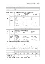
Page 207: ...this product If the smaller power is needed for handling the load you can disable the energization for some power units to reduce the power consumption of this product If there is a power unit on whic...

Page 208: ...TER key The power unit energization setting window opens 3 Enable Disable the energization The power unit on which the energization is enabled disabled is represented by respectively Move the cursor t...

Page 209: ...r and the RMS current limiter are restored to the factory default settings corresponding to the rated power which is determined by the number of the power units to be energized For the polyphase outpu...

Page 210: ...the Beep item to turn the beep sound on or off 4 26 Changing the Background Color and the Contrast of the Screen You can change the background color and the contrast of the liquid crystal display LCD...

Page 211: ...he window for adjusting the LCD Following two methods are available a Shortcut operation b Press the MENU key to move to the root menu then select System The system setting window opens Put the cursor...

Page 212: ...default setting Output on off Off Output range 100 V range AC DC mode AC mode Signal source INT External synchronization signal LINE or EXT LINE AC voltage setting 0 V Frequency 50 Hz Output waveform...

Page 213: ...nterface USB External control Disable Clipped sine wave Clip ratio specified Clip ratio 100 Crest factor 1 41 Arbitrary Waveform Memory ARB1 to 8 Triangle wave ARB9 to 16 Square wave Sequence paramete...

Page 214: ...or on Exec next to the Reset item then press the ENTER key The reset operation is performed Notes If you reset the product the content in the Basic Setting Memory will not be cleared Once restarted th...

Page 215: ...DP060LM DP120LM DP180LM 197 5 Description of Screen and Menu 5 1 Screen Configuration 198 5 2 Menu Composition 202...

Page 216: ...DC mode Signal source 3 4 2 d Output phase configuration Current output phase configuration 1P2W Single phase two wire 1P3W Single phase three wire 3P4W Three phase four wire 1 2 e Status icon The are...

Page 217: ...tivated 4 1 2 Peak current limiter The peak current limiter is activated 4 1 1 Active wattage limiter The active wattage limiter is activated 4 1 5 Synchronization With SYNC the internal signal source...

Page 218: ...nsing terminal SVmax Maximum peak value of the voltage on the sensing terminal SVmin Minimum peak value of the voltage on the sensing terminal I 2 Output current effective value Iavg 4 Average DC valu...

Page 219: ...ee wire L2 phase in the unbalanced mode single phase three wire All phases in the balanced mode three phase phase voltage setting All phases in the balanced mode three phase line voltage setting L1 ph...

Page 220: ...unction are shown in Table 5 5 You can open each menu by using a soft key Table 5 5 Menus of the Continuous Function Menu Description Refer to Osc 1 AC DC Switches the AC DC mode 3 4 2 2 Source Switch...

Page 221: ...trigger output File Store Saves to clears and renames the Sequence Memory Recall Recalls the Sequence Memory Clear Resets the edited sequence to the factory default settings Compile Compiles the edit...

Page 222: ...simulation It is displayed in the output on and simulation stopped states Stop Ends the simulation It is displayed in the Simulation running state Measure Makes the measured value display settings It...

Page 223: ...tor Makes the Monitor function settings 4 10 Ext Control Switches the control by the external control function to Enable Disable DevCtrl 4 18 Remote Makes the communication interface settings 6 1 Rela...

Page 224: ......

Page 225: ...DP060LM DP120LM DP180LM 207 6 Remote Control 6 1 Communication Interface 208 6 2 Remote Local State Switching 216...

Page 226: ...s the Virtual Instrument Software Architecture VISA library If you do not have a license to use VISA library you need to obtain one generally it requires some cost For details of the remote control co...

Page 227: ...the cursor on Setup next to the Remote item then press the ENTER key The remote setting window opens 3 In the Interface item select USB 4 The window shows Terminator and USB ID For the USB ID see the...

Page 228: ...rly About USB ID Used for a system connected with multiple DP series programmable AC power sources through USB to enable the application identify each source The USB ID is represented in the following...

Page 229: ...unication Interface DP060LM DP120LM DP180LM 211 2 Put the cursor on Setup next to the Remote item then press the ENTER key The remote setting window opens 3 In the Interface item select RS232 4 Set ea...

Page 230: ...efore connecting or disconnecting the cable Binary transmission is not supported 6 1 3 GPIB This product is compliant with the GPIB IEEE Standard 488 1 1987 The GPIB based remote control is available...

Page 231: ...n a place under electrically noisy environment Before connecting or disconnecting the cable turn off the power to all devices on the bus When using the GPIB turn on the power to all devices on the bus...

Page 232: ...1 Connect this product and computer with LAN cable LAN connector is available on the rear of this product Turn off this product and the computer before connecting or disconnecting the cable 2 Press t...

Page 233: ...and Gateway are displayed When not using fixed IP is displayed because it is uncertain except for MAC Address immediately after interface switching After assignment the display such as IP Address wil...

Page 234: ...can check the IP address of the gateway repeater to use implicitly Notes Avoid use in a place under electrically noisy environment Turn off this product and the computer before connecting or disconne...

Page 235: ...DP060LM DP120LM DP180LM 217 7 Options 7 1 Remote Controller 218 7 2 Fixing Bracket 218 7 3 Replacement Air Filter 219 7 4 Power Cable 220...

Page 236: ...er External View 7 2 Fixing Bracket The fixing bracket which fix this product to the floor They can be requested at the time of order or added after the purchase Table 7 1 Fixing Bracket Model Names M...

Page 237: ...cription Number of used sheets DP060LM DP120LM DP180LM PA 001 2792 Replacement Air Filter 1L For the Front grill 1L 1 sheet 1 1 1 PA 001 2793 Replacement Air Filter AL For the Front grill AL 1 sheet 0...

Page 238: ...tion board to connect the cable firmly The power cable is dedicated only to this product Do not use it with any other product Table 7 3 Power Cable Model Names Model name Power input Rated output Maxi...

Page 239: ...DP060LM DP120LM DP180LM 221 8 Peripherals 8 1 Peripherals Line up 222 8 2 Using in Combination with DIP or RIN 223...

Page 240: ...ltage dips tests complying with IEC 61000 4 11 can be performed In addition Large capacity model is also available for IEC 61000 4 34 test In this document it is written as DIP When using this product...

Page 241: ...te sensing function of this product Turn off this product including its peripherals before connecting or disconnecting the cable Be sure to turn off this product and switch off the breaker at the dist...

Page 242: ...t have the same electric potential within this product Place DIP or RIN near this product The cable connecting between the output terminal of this product and the input terminal of DIP or RIN should b...

Page 243: ...and DP4162 RIN in Single phase Output CONTROL I O connector FEEDBACK cable Included in DIP Sensing input terminal FEEDBACK connector DP060LM DP4172 DIP CONTROL IN connector Control cable 25 pin Inclu...

Page 244: ......

Page 245: ...DP060LM DP120LM DP180LM 227 9 Troubleshooting 9 1 Error Messages and Error Handling 228 9 2 When a Failure is Suspected 235...

Page 246: ...r 9 1 5 d Message Describes the error details 9 1 5 e Press Enter Key Displayed for an error whose protection type is Output Off 9 1 2 f Soft key PU ON Displayed for an error that occurred on the powe...

Page 247: ...ror message window press the PU ON soft key The power unit energization setting window opens 2 The power unit with an error is marked with E like Check on the power unit that has an error First leavin...

Page 248: ...power of it Output Off The output turns off The panel says Output OFF and Press Enter Key When you press the ENTER key you will return to the previous window for further operations if the cause of the...

Page 249: ...ich does not allow the setting execution Enter the signal frequency within the range 13 Auto Cal Disabled Message display only The Autocal setting becomes off because of out of the calibration range 1...

Page 250: ...rporation or our agent from whom you purchased the product 43 Mismatched Pw Unit Versions System Lock All power unit versions do not match 44 Unsupported Pw Unit Version System Lock A power unit of un...

Page 251: ...and thus the output was turned off according to the setting 59 Current Limiter Peak Output Off The peak current limiter was activated and thus the output was turned off according to the setting 60 Po...

Page 252: ...ence compilation failed 83 Simulation Compile Error Message display only Simulation compilation failed 84 System Updated Please Reboot System Lock The setting of output phase configuration changed Or...

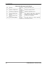
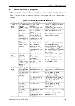
Page 253: ...D display is completely invisible perform the Shortcut operation to adjust the contrast Then the digit cursor is placed on the tenths place 4 26 Problem at key operation Panel operations cannot be per...

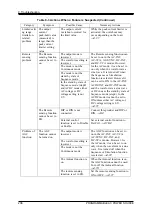
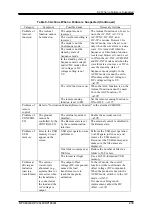
Page 254: ...voltage does not come up The state is the output off the OUTPUT key LED illuminates Press the OUTPUT key to turn the output on The output voltage is set to zero Check for the output voltage setting 3...

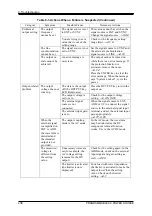
Page 255: ...nt panel air inlet or rear panel air outlet there is something blocking the air flow Install the product so as to satisfy the installation conditions described in 2 2 Measurement function related prob...

Page 256: ...the ACDC mode it cannot be set to ON unless either AC voltage or DC voltage setting is 0 V 4 11 The waveform setting is incorrect The mode is not the Continuous mode The mode is not the stand by stat...

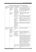
Page 257: ...function is set to FB Set the remote sensing function to ON or OFF 4 11 Problem of remote control Refer to Instruction Manual Remote Control in the attached CD ROM Problem of CONTROL I O The product...

Page 258: ...current or conversely set it to a sufficiently large value to disable the limiter to be activated or sufficiently reduce the amplitude before turning off the output 4 1 1 Memory function related probl...

Page 259: ...DP060LM DP120LM DP180LM 241 10 Maintenance 10 1 Preface 242 10 2 Daily Maintenance 242 10 3 Storage Repackaging Transportation 244 10 4 Checking Firmware Version 244...

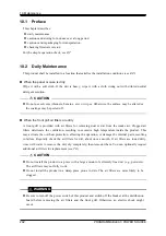
Page 260: ...ving dust or dirt from the intake air Clogged air filters deteriorate the ventilation resulting in excessive high temperature inside the product This may activate the overheat protection affecting the...

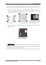
Page 261: ...washers behind Turn and loosen the screw carefully until the corner comes free from the body In case that a retaining washer behind comes free from the screw push it with a nut driver and attach it t...

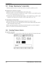
Page 262: ...e change or direct sunlight Store it under a normal temperature environment wherever possible For the storage condition see 11 32 Repackaging and transportation Follow the instructions below when repa...

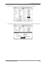
Page 263: ...P120LM DP180LM 245 2 Put the cursor on View next to the Information item then press the ENTER key 3 The Information window opens The firmware version is shown at the Firmware Version item Note This is...

Page 264: ......

Page 265: ...ting 259 11 14 Current Limiter 260 11 15 Setting Range Limit Function 262 11 16 Remote sensing 263 11 17 AGC 264 11 18 Autocal 265 11 19 Sequence 266 11 20 Simulation 267 11 21 Clipped Sine Wave 268 1...

Page 266: ...noted A value with the accuracy is the guaranteed value of the specification However an accuracy noted as reference value shows the supplemental data for reference when the product is used and is not...

Page 267: ...he signal source and amplification section of this product are DC coupled and the DC component is also amplified The AC and DC output settings of 1 Hz or higher are available The signal sources that c...

Page 268: ...es Cannot be selected in the ACDC mode SYNC Uses the internal signal source Synchronizes the frequency of the internal signal source with the signal EXT from the external synchronization signal input...

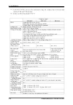
Page 269: ...types clipped sine wave 3 types Output on phase setting range 0 0 to 359 9 variable Setting resolution 0 1 Output off phase setting range 0 0 to 359 9 variable active inactive selectable Setting reso...

Page 270: ...hase current 12 Peak value Apk which is four times of the maximum current Peak value Apk which is three times of the maximum current Short reverse power flow 13 14 100 or less of Maximum current RMS r...

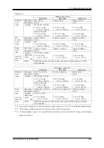
Page 271: ...maximum current and the operating temperature 16 For 40 Hz to 550 Hz sine wave the rated output voltage the resistance load for the maximum current at 55 Hz and 55 Hz reference 17 Set for the L1 phas...

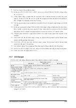
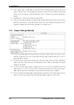
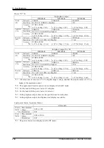
Page 272: ...ut Within 0 15 V 0 30 V 45 Hz to 65 Hz Within 0 15 V 0 30 V 40 Hz to 550 Hz Within 0 5 V 1 0 V Fluctuation with ambient temperature Phase voltage 27 Within 0 01 C typ 24 In the case of single phase an...

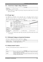
Page 273: ...80 V phase voltage 220 V 15 with limited to 433 V phase voltage 250 V or lower Frequency 50 Hz 2 Hz or 60 Hz 2 Hz Power factor 29 0 90 or higher typ Efficiency 29 77 or higher typ Maximum power consum...

Page 274: ...Hz 2 of rdg 1 V 2 V 45 Hz to 65 Hz 2 of rdg 1 V 2 V 30 The accuracy values are in the case that the output voltage is within voltage setting range 31 In the polyphase output it is a specification for...

Page 275: ...m values of max and min with the polarity with the clear function Polyphase output 36 DP060LM DP120LM DP180LM Effective value rms Full scale 26 67 A 13 33 A 53 33 A 26 67 A 80 A 40 A Resolution 0 01 A...

Page 276: ...Apparent VA Full scale 3000 VA 6000 VA 9000 VA Resolution 0 1 VA 1 VA 1000 W or higher 1 VA Accuracy 45 Hz to 65 Hz 2 of rdg 3 VA 2 of rdg 4 VA 3 of rdg 6 VA Reactive var Full scale 3000 var 6000 var...

Page 277: ...le 26 67 A 13 33 A 100 53 33 A 26 67 A 100 80 A 40 A 100 Resolution 0 01 A 0 1 0 1 A 0 1 Accuracy At RMS reference value Up to 20th 1 of rdg 0 3 A 0 2 A 1 of rdg 0 55 A 0 3 A 2 of rdg 0 8 A 0 4 A 21st...

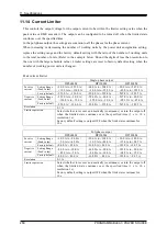
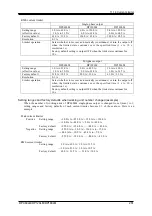
Page 278: ...y default 252 0 A 126 0 A 504 0 A 252 0 A 567 0 A 283 5 A Negative current Setting Range Peak value 252 0 A to 30 0 A 126 0 A to 15 0 A 504 0 A to 60 0 A 252 0 A to 30 0 A 567 0 A to 90 0 A 283 5 A to...

Page 279: ...31 5 A Resolution 0 1 A Limiter operation Select whether to recover automatically continuous or turn the output off when the limited state continues over the specified time 1 s to 10 s resolution 1 s...

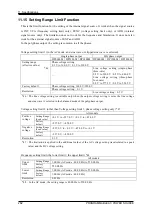
Page 280: ...actory default Phase voltage setting 160 0 V 320 0 V Resolution Phase voltage setting 0 1 V Line voltage setting 0 2 V 46 The line voltage setting is available only when the output voltage setting is...

Page 281: ...tting is 0 V for ACDC INT Also if the Remote sensing is ON remote sensing is turned OFF once when you change ACDC mode from AC mode of DC mode even in stand by state Turn ON it again when you need Whe...

Page 282: ...ng to FB AGC cannot be set see 11 16 Effective only for AC INT AC VCA AC SYNC DC INT and DC VCA and when the waveform is sine wave or DC It is turned off when the Sequence or Simulation is selected It...

Page 283: ...t voltage setting Effective only for AC INT AC VCA AC SYNC DC INT and DC VCA and when the waveform is sine wave or DC It is turned off when the Sequence or Simulation is selected It cannot be selected...

Page 284: ...angle Step termination Jump count 1 to 9999 or infinite Specification of the Jump to step Synchronous step output 2bit Specification of the branch step Trigger output Sequence control Start Stop Hold...

Page 285: ...ll models Number of memories 5 non volatile Number of steps 6 Initial Normal 1 Trans 1 Abnormal Trans 2 Normal 2 Setting range of Step Time 0 0010 s to 999 9999 s 0 s is available only for the Transit...

Page 286: ...In the polyphase output it is the setting for phase voltage 57 The crest factor is represented as voltage peak value voltage effective value It is 1 41 for sine wave 58 When the clip ratio is specifie...

Page 287: ...ctive maximum input voltage 10 V 11 23 2 Voltage Setting Signal Input Signal Source VCA only This is the signal to set the output voltage amplitude of the internal signal source DC input Output voltag...

Page 288: ...to 100 Hz other than sine wave 61 In the DC mode only in single phase output or 45 Hz to 65 Hz factory default gain rated output voltage and no load 11 24 General Function Description Factory default...

Page 289: ...gnal source INT External synchronization signal LINE or EXT LINE AC voltage setting 0 V Frequency 50 Hz Output waveform Sine wave Output on phase and output off phase 0 0 Phase voltage Line voltage se...

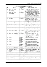
Page 290: ...rnal software Output phase configuration check Checks the output phase configuration While energizing Description Abnormal output Turns off the panel display and output when an output overvoltage or o...

Page 291: ...value Falling Clear State output Output level TTL 66 Output impedance 220 Polarity 67 Positive or negative negative Status Power On Off Low Off High On Output On Off Low On High Off Negative Low Off H...

Page 292: ...sub 25 pin multi connector Rear panel Female M2 6 screw CONTROL SIGNAL D sub 37 pin multi connector Rear panel Female M2 6 screw QUICK CHANGE SYNC OUTPUT BNC connector Rear panel unbalanced STATUS OUT...

Page 293: ...N interface IEEE802 3 LXI 1 4 Core 2011 73 Item Description or Selection Factory default Terminal RJ 45 modular jack Transmission method Ethernet 100BASE TX 10BASE T Communication protocol SCPI RAW Te...

Page 294: ...ut Number of working power units 6 5 4 3 2 1 2 1 Monitored Output phase voltage or output phase current switched Gain Phase voltage V V 400 1 200 1 Phase current V A 150 1 300 1 100 1 200 1 50 1 100 1...

Page 295: ...electromagnetic emissions using this product in a residential area must be avoided 79 For compliant manufacturing lot please contact us or our agent 11 32 Operation Environment All models Operation E...

Page 296: ...ypad and jog shuttle On order and after purchase Fixing Bracket PA 001 2973 Type2L cabinet for fixing front rear left and right side PA 001 2971 Type4L cabinet for fixing front and rear side PA 001 28...

Page 297: ...ir Filter 3L For front grill 3L 1sheet 1 0 0 PA 001 2970 Replacement Air Filter 4L For front grill 4L 1sheet 0 1 0 Front grill 1L Replacement Air Filter 1L Front grill AL Replacement Air Filter AL Fro...

Page 298: ...11 Specifications PROGRAMMABLE AC POWER SOURCE 280 11 35 Outline Dimensional Drawing Figure 11 2 DP060LM Type2L cabinet...

Page 299: ...11 35 Outline Dimensional Drawing DP060LM DP120LM DP180LM 281 The stabilizer accessory is installed Figure 11 3 DP120LM Type4L cabinet...

Page 300: ...11 Specifications PROGRAMMABLE AC POWER SOURCE 282 Figure 11 4 DP180LM Type5L cabinet...

Page 301: ...83 199 Autocal 164 199 AVG 55 balanced mode 50 Basic Setting Memory 141 204 beep 192 205 branch step 75 busy 199 calibration 26 CANCEL key 32 37 caster 12 28 CF 55 134 200 character string entry box 3...

Page 302: ...54 200 Imin 54 200 Immunity Test Software 5 222 Information 205 245 Initial Step 104 Inrush Current 130 Installation Environment 9 INT 43 Intra Step parameter 72 105 Ipk Hold 54 132 200 Jog 32 Jump co...

Page 303: ...0 phase current 54 61 200 phase voltage 50 61 169 200 Polyphase 20 50 Polyphase output terminal 30 power cable 14 220 power factor 55 200 power input terminal 14 30 power on off 32 power switch 28 pow...

Page 304: ...4 Step sync code output 75 106 step termination 75 Step Time 74 105 Step control parameter 72 105 Stop Phase 76 106 storage 244 SV 160 200 SVavg 200 SVmax 200 SVmin 200 Sweep 73 SYNC 43 183 synchroniz...

Page 305: ...en corresponding to following particulars A Failure caused by improper handling or use of the product in a manner that does not conform with the provisions of the Instruction Manual B Failure or damag...

Page 306: ...tion provided in this manual is intended to be accurate and reliable However we assume no responsibility for any damage regarding the contents of this manual We assume no responsibility for influences...

Page 307: ...http www nfcorp co jp NF Corporation 6 3 20 Tsunashima Higashi Kohoku ku Yokohama 223 8508 JAPAN...

Reviews: