3.
Basic Operation
PROGRAMMABLE AC POWER SOURCE
34
3.2.4
The Settings Loaded after Startup
For the Continuous function, the output settings are invoked from the Basic Setting Memory No.1
and other settings are loaded from the System Setting Memory. For details, see
4.8
and
11.25.
For the Sequence function and the Simulation function, the factory default settings are loaded for the
content of each step.
3.2.5
Checking the output phase configuration
On the screen after startup, the output phase configuration icon is displayed in the position shown in
the screen below. This case is single-phase output. See
3.4.1
about the setting output phase
configuration.
Display of output phase configuration
3.2.6
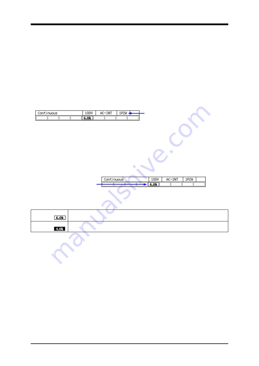
Checking the Rated Power
On the screen after startup, the rated power icon is displayed in the position shown in the the screen
below. The value in the icon indicates the maximum electric power that can be output. In this case,
the maximum electric power is 6.0 kVA.
If the rated power is restricted by the power unit energization setting, the icon is highlighted as
shown in Table 3-4. For detailed information about the power unit energization setting, see
4.23
.
Rated power icon
Table 3-4 How the Rated Power Icon is Displayed Depending on the Power Unit
Energization Setting
Normal icon
Example
:
All power unit energization settings are enabled. The rated power is set to the
maximum value that the model system and the power supply voltage can provide.
Highlighted icon
Example:
Because some power unit energization settings are disabled, the rated power is
restricted.
--------
Notes
------------------------------------------------------------------------------------------------------------
For a polyphase output, the rated power is displayed for each phase.
-----------------------------------------------------------------------------------------------------------------------------
3.2.7 Power
Off
Disable the output and ensure the OUTPUT LED is off before pressing "Off" side of the power
switch. All screens disappear and all LEDs turn off, then the power input and the output are blocked
inside the system.
Summary of Contents for DP060LM
Page 1: ...PROGRAMMABLE AC POWER SOURCE DP060LM DP120LM DP180LM INSTRUCTION MANUAL NF Corporation...
Page 2: ......
Page 3: ...PROGRAMMABLE AC POWER SOURCE DP060LM DP120LM DP180LM INSTRUCTION MANUAL DA00059920 004...
Page 4: ......
Page 19: ...DP060LM DP120LM DP180LM 1 1 Outline 1 1 Overview 2 1 2 Series Lineup 2 1 3 Features 3...
Page 24: ......
Page 224: ......
Page 244: ......
Page 264: ......
Page 300: ...11 Specifications PROGRAMMABLE AC POWER SOURCE 282 Figure 11 4 DP180LM Type5L cabinet...

